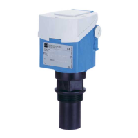
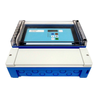
Mounting Prosonic T
6 Endress+Hauser
2.3 Installation conditions
2.3.1 Installation conditions for level measurements
L00-FMU30xxx-17-00-00-xx-005
• Do not install the sensor in the middle of the tank (3). We recommend leaving a distance
between the sensor and the tank wall (1) measuring 1/3 of the tank diameter.
• Protect the device against direct sun or rain (2).
• Avoid measurements through the filling curtain (4).
• For solid application where bulk solid cones appear, align the sensor membrane perpendicular
to the surface.
• Make sure that equipment (5) such as limit switches, temperature sensors, etc. are not located
within the emitting angle α. In particular, symmetrical equipment (6) such as heating coils,
baffles etc. can influence measurement.
• Never install two ultrasonic measuring devices in a tank, as the two signals may affect each
other.
• To estimate the detection range, use the 3 dB emitting angle α.
Sensor α L
max
r
max
1½" 11° 5 m (16 ft) 0.48 m (1.6 ft)
2" 11° 8 m (26 ft) 0.77 m (2.5 ft)
1
23
4
5
6
1/3D
D
r
a
L

 Loading...


