Soliphant M FTM50, FTM51, FTM52
Endress+Hauser 7
Electrical connection Two-wire AC connection
Output signal
Signal on alarm Output signal on power failure or in the event of device failure: I
R
Connectable load • For relays with a minimum holding power/rated power > 2.5 VA at 253 V (10 mA) or > 0.5 VA at 24 V
(20 mA)
• Relays with a lower holding power/rated power can be operated by means of an RC module connected in
parallel
• For relays with a maximum holding power/rated power < 89 VA at 253 V or 8.4 VA at 24 V
• Voltage drop across FEM51 max. 12 V
• Residual current with blocked thyristor max. 4 mA (5.5 mA for short fork)
• Load current max. 350 mA (short-circuit proof)
Always connect in series with a load!
Check the following:
• the residual current consumption in blocked state
• that for low voltage
– the voltage drop across the load is such that
the minimum terminal voltage at the electronic
insert (19 V) when blocked is not undershot.
– the voltage drop across the electronics when
switched through is observed (up to 12 V)
• that a relay cannot de-energise with holding
power below 1 mA.
If this is the case, a resistor should be connected
parallel to the relay (RC module available on
request).
• When selecting the relay, pay attention to the
holding power / rated power
(See below "Connectable load")
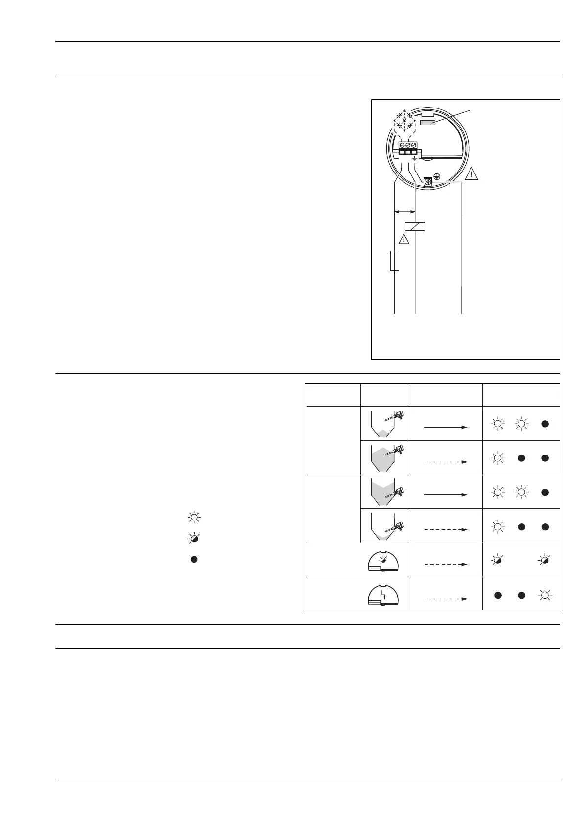
L00-FTM5xxxx-04-05-xx-en-004
F
1A
R
12
L1
U~ max. 253 V
50/60 Hz
(AC)
NPE
(Ground)
min.
19 V
*
*
FEM51
External load R
be connectedmust
I
L
I
R
L00-FTL5xxxx-07-05-
xx-xx-000
= load current
(switched through)
= residual current
(blocked)
= lit
= flashes
= unlit
L00-FTM5xxxx-04-05-xx-en-001
* See also "Operating elements"
on Page 22.
12
12
12
12
12
12
I
L
I
L
I
R
I
R
I
L
/I
R
I
R
MAX
MIN
MAX
MIN
Instrument failure
Maintenance
required *
Safety mode
Level
Output signal
LEDs
green yellow red
 Loading...