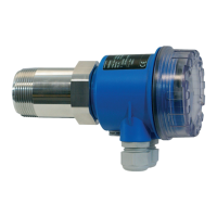
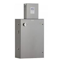
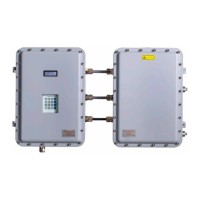
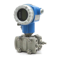
Soliwave FDR56/FQR56
14 Endress+Hauser
Electrical connection
5 Electrical connection
For a device for the hazardous area:
Observe the instructions in the Ex documentation (XA).
5.1 Connection requirements
The following points must be observed before connecting the device:
• The voltage supply must match the voltage specied on the nameplate.
• Switch o the supply voltage before connecting the device.
• When using the public powers supply, install an easy accessible power switch in the proxi-
mity of the instrument. Mark the power switch as a disconnector for the instrument (EN/
IEC 61010).
• The cable glands and connectors are permitted for connecting xed cables and lines only.
The operator must ensure adequate strain relief.
• The device is to be attached so that the cable gland is protected from mechanical damage
(degree of mechanical hazard "low" – impact energy: 4 joules).
• Seal unused entry glands with approved sealing plugs that correspond to the type of protec-
tion. The plastic transport sealing plug does not meet this requirement and must therefore
be replaced during installation.
5.1.1 Connect potential equalization
• The potential equalization must be connected to the external ground terminal on the device.
• For optimum electromagnetic compatibility, keep the potential equalization line as short as
possible.
• The recommended cable cross-section is 2.5mm
2
.
• The potential equalization of the FDR56/FQR56 must be included in the local potential
equalization.
5.1.2 Connecting cable requirements
• Permissible temperature range → 10
• Normal installation cable sufficient
• Cable cross-sections: 0.2 to 2.5mm
2
(24 to 12 AWG)
Cable gland
• Clamping range:
- 5 to 10mm (0.2 to 0.39in) acc. to EN 50262 or 7 to 10mm (0.28 to 0.39in) acc. to
UL-514 B (Cable gland made of plastic)
- 7 to 10.5mm (0.28 to 0.41in) (Cable gland made of metal)
• Tightening torque
- Max. 6 Nm (Cable gland made of plastic)
- Max. 10 Nm (Cable gland made of metal)
For the optionally supplied mating M12 connectors, the following requirements apply:
• Clamping range of the cable: 6 to 8mm (0.24 to 0.31in)
• Cable cross-sections: Max. 0.75mm
2
(18 AWG)

 Loading...


