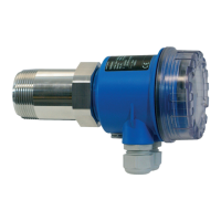
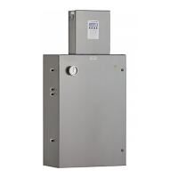
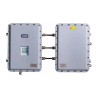
Soliwave FDR56/FQR56
22 Endress+Hauser
Commissioning
• The Soliwave microwave barrier is adjusted, if with maximum covered path a) on devices
with switching output the switching point (LED 5) is undercut safely or b) on devices with
current output all 10 LEDs are not lit.
• A repeated automatic adjustment (function 1 or function 2) resets any adjustment carried
out earlier.
7.2.2 Adjustment with maximum covered path (function 2)
This automatic setup function can be used if the path is maximum covered.
Move the encoding switch to position 2
→ Display of the function number
→ Aer 2 seconds: Display of the current signal strength, example:
Simultaneously press the operation buttons on the device with maximum covered path
→ Automatic adjustment is carried out
→ Display of the signal strength aer adjustment
Move the encoding switch to the initial position 0
→ Display of the current signal strength
Optional:
Additional manual adjustment with free or minimum covered path (function 3)
For most applications the automatic setup is sucient. The manual setup can be used to adapt
the microwave barrier individually to the application or medium.
If aer an automatic setup with covered path (function 2) the condition "free path" can not be
detected safely (switching point of the limit detection is not exceeded with free or minimum
covered path), the sensitivity must be increased with this manual setup function 3.
Move the encoding switch to position 3
→ Display of the function number
→ Aer 2 seconds: Display of the current signal strength, example:
Press the opartion buttons on the device to achieve an increase or reduction of the signal
strength display with free or minimum covered
→ Display of the signal strength with free or minimum covered path (all 10 LEDs illumi-
nate)

 Loading...


