EasyManuals Logo

Endress+Hauser SpectraSensors SS500 Hardware Installation And Maintenance Manual

Endress+Hauser SpectraSensors SS500
121 pages
To Next Page IconTo Next Page
To Previous Page IconTo Previous Page
Page #95 background imageLoading...
Page #95 background image
Maintenance and Troubleshooting
Hardware Installation and Maintenance Manual B
11
11. Dismount the cell from the bracket by removing the four securing
screws (two on top, two on the bottom) using a 9/64 in. Allen
wrench. Place the measurement cell on a clean, flat surface with the
pressure sensor facing up. Refer to Figure B–5 below.
Orient the measurement cell to avoid any debris from entering the
cell.
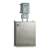
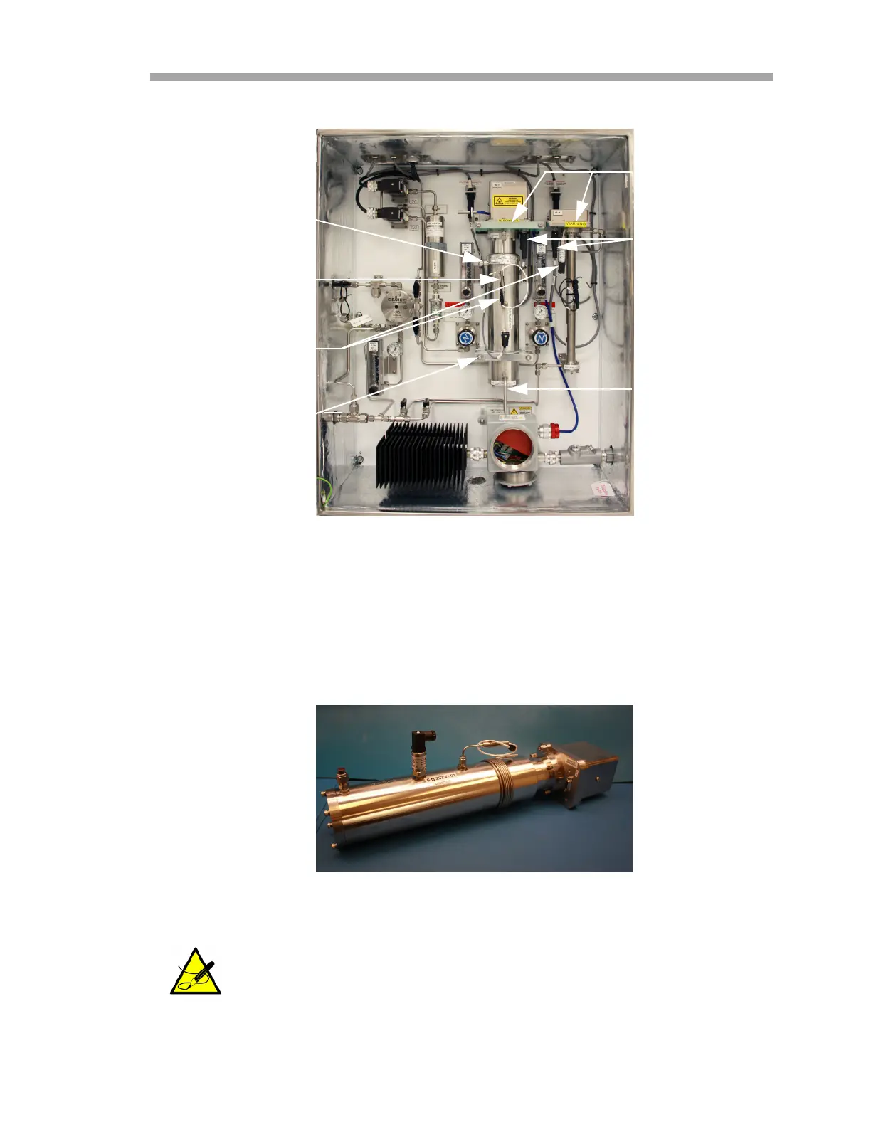
Figure B–4 SCS cabinet interior
OPTICAL CABLE
HARNESS
THERMISTOR
CABLE
CELL OUTLET
CELL INLET
(8/28 m CELL)
MOUNTING
BRACKET
MOUNTING
BRACKET
PRESSURE
SENSOR
CABLE
Figure B–5 Removed 28 m measurement cell

Table of Contents

Other manuals for Endress+Hauser SpectraSensors SS500

Questions and Answers:

Question and Answer IconNeed help?

Do you have a question about the Endress+Hauser SpectraSensors SS500 and is the answer not in the manual?

Endress+Hauser SpectraSensors SS500 Specifications

General IconGeneral
BrandEndress+Hauser
ModelSpectraSensors SS500
CategoryMeasuring Instruments
LanguageEnglish

Related product manuals