Turbimax CUS71D Device description
Endress+Hauser 13
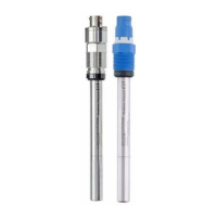
5 Device description
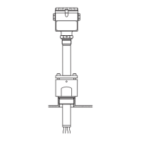
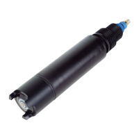
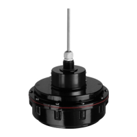
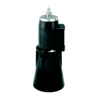
5.1 Sensor design
The sensor is designed for continuous in-situ determination of interfaces.
The sensor includes all necessary modules:
• Power supply
• Ultrasonic source sends the measurement signals.
• Ultrasonic receiver receives the measurement signals, digitalizes and converts the signals to a
measurement value.
• The microcontroller of the sensor controls the internal operations and the data transmission.
All data - including calibration data - are stored in the sensor. That means:
• A pre-calibrated sensor can be used at the measuring point.
• The sensor can be calibrated externally.
• The sensor can be used at multiple measuring points with different calibration data.
5.2 Measuring principle
A piezoelectric crystal is integrated in a flat cylindrical plastic housing. When the crystal is excited
by an electrical voltage, it generates a sonar signal. The ultrasonic waves are transmitted at a
frequency of 657 kHz at an angle of 6° to scan the separation zones.
The parameter measured is the time it takes for the transmitted ultrasonic signal to reach the solid
particles in the separation zone and return to the receiver.
A sensor version with wiper avoids film formation at the sensor membrane. If a turbidity signal is
also needed a sensor version with wiper and integrated turbidity measurement is available.
5.3 Function
The speed of the sound varies according to the physical properties of the measuring medium and is
affected by temperature and air pressure. The liquid zones and solids content of the medium also
vary.
To obtain precise measurement results, it is therefore vital to adapt system variables to the process,
e. g. pulselength and the speed of the sound.
The CM44x offers the following possibilities for signal evaluation:
• Mask out regions where the separation zone is not expected.
• Evaluate received signal strengths differently.
• Select leading or trailing signal edges in the evaluation.
• Amplify sensor signals at different rates, e. g. for floating sludge.
• Define a region (gate) above and below the separation zone. Signal evaluation only takes place in
the defined region. The gate wanders with the separation zone. This makes smoothing algorithms
unnecessary.
• Arrow indicator for basin floor.
5.4 Sensor monitoring
The optical signals are continuously monitored und checked for plausibility.
Discrepancies are reported via error messages by the transmitter.
The sensor check system of the Liquiline CM44x reports the following failure conditions:
• Implausible high or low measuring values
• Disturbed controlling due to erroneous measuring values

 Loading...