16
Temperature is controlled using the ventilation unit’s
own automatic control. The ventilation unit controls the
circulation pump and the 3-way valve.
To install:
1. Install the cooling coil in the outside air duct.
2. Connect the condense water outlet.
3. Build a separate pump group for circulating cool
brine adjacent to the ventilation unit cooling coil.
4. Isolate the pipes carefully with vapour proof
insulation to prevent condensation on the outside
of the pipes in warm and semi-warm spaces.
5. Install a heat exchanger in the coil system.
6. Install and connect the outside air temperature
sensor (TE01) in the outside air duct before the
duct coil.
7. Prepare / connect wiring between the ventilation
unit, the geothermal pump and the actuator.
Refer to the electrical connection diagrams at the
end of this manual.
eWind external connections
Connection/Functionality
Location
on eWind
controller card
Voltage/current Cable (example) Wiring outside AHU
AI NTC
TE01 Outside air temperature TE01 3.3VDC Quick connector 5m
cable supplied with AHU
Yes, if pre-heater/
preecooler (CHG/
AGH) or electrical duct
mounted pre-heater
TE10 Supply air temperature TE10 3.3VDC Quick connector 5m
cable supplied with AHU
Yes, if duct heater/
cooler coil
TE45/TE46 Heating/cooling coil
return water temperature
TE45 3.3VDC Quick connector 5m
cable supplied with AHU
Yes, if duct heater/
cooling coil (W/E-CG)
Digital outputs DO Potential free contact
ON/OFF Control for heating DO2 Max 250VAC/50VDC
8A/2A inductive load
MMJ 3x1.5 Yes, if hydronic heating
(W)
ON/OFF Control for dampers DO5 Max 250VAC/50VDC
8A/2A inductive load
MMJ 3x1.5 Yes
A alarm output (NO) (Default)
ON/OFF Control for pre-
heating (CHG/AGH or electrical
pre-heater)
ON/OFF Control for cooling (CG)
DO8 Max 250VAC/50VDC
8A/2A inductive load
MMJ 3x1.5 Yes, except built in pre-
heater coil
Analog inputs AI
%RH or CO2 external transmitter AI1 (user
congurable)
0-10VDC KLM 4x0.8 Yes
Analog Outputs AO
Control voltage for heating AO5 0-10VDC 10mA KLM 2x0.8 Yes, if hydronic heating
(W)
Control voltage for pre-heater /
Control voltage for cooling
(CHG/CG)
AO6 0-10VDC 10mA KLM 2x0.8 Yes, except built in
pre-heater
Digital inputs DI Potential free NO
contact
Emergency stop DI1 (xed) 24VDC KLM 2x0.8 Yes
Manual boost mode DI4 24VDC KLM 2x0.8 Yes
Away mode DI5 24VDC KLM 2x0.8 Yes
Overpressure mode DI6 24VDC KLM 2x0.8 Yes
Miscellaneous connections
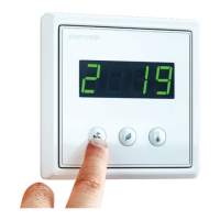
Operating panel connectors OP1, OP2 10m cable supplied with
AHU
Yes
Modbus-RTU X26 Instrumentation cable
2x2x0.5
Yes
The functions and accessories listed in the following table may need external wiring or connecting to function:
 Loading...