18
External sensors
It is possible that external sensors must be installed
depending on model of ventilation unit.
• The sensor element for duct mounted
temperature, RH and CO2 sensors must be
installed inside the duct.
• Most temperature sensors are supplied with a
readymade 5m long cable.
• RH and CO2 sensors need wiring on site.
To install:
1. Choose the place for the sensor according to the
unit of measurement that is to be measured.
Refer to the control diagram at the end of this
manual.
2. Place the sensor in the duct at a straight segment,
at least 2x the duct Ø before and after any duct
coil, bends or ttings.
3. Drill a suitable hole for the sensor and a rubber
grommet in the duct.
4. Push sensors attached to a cable trough the
rubber grommet so that the sensor element is a
few centimetres inside the duct.
The rubber grommet must be air tight, and tight
enough that the sensor cable cannot slip through
by itself.
• You can use a cable tie to lock the sensor in
place.
5. Install sensors with rigid pipe type sensor elements
through an adjustable ange mounted to the duct.
• Push the sensor element through the ange
and lock in place with a screw at suitable
depth.
• Conduct electrical connections according to
the electrical schematics at the end of this
manual.
• The functions and accessories listed in the
table "eWind external connections" on page
16 may need external wiring or connecting
to function:
• Make sure the cable grommets in the duct and
ventilation unit are absolutely air and water
tight. If in doubt, use an elastic sealer to seal
the grommets.
6. To select a CO2 sensor active the CO2 boosting
function must be selected "on" from parameter
c27.
For more information on electrical connections, see
the control and connection diagrams at the end of this
manual.
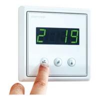
Installing eWind control panel
The eWind control panel (see chapter "Control system,
eWind operating panel" on page 26) is installed
in a wall mounted recessed junction box, or using
the supplied surface mounted junction box. One
ventilation unit can be controlled with the maximum of
2 panels.
Installing one control panel
To install:
1. Install the connection cable supplied with the unit.
2. Attach the connection cable to the connector on
the eWind control panel.
3. Install the eWind control panel to the wall junction
box.
4. Attach the connection cable to connector OP1 of
the eWind controller card.
• Make sure the cable grommets in the ventilation
unit are absolutely air and water tight.
• If in doubt, use an elastic sealer to seal the
grommets.
Installing two control panels
If the ventilation unit is controlled with two control
panels, each panel is attached to the eWind controller
card with its own cable.
To install:
1. Install the eWind control panels as instructed
above. Attach the connection cable of the rst
eWind panel to connector OP1 and cable of the
second eWind control panel to connector OP2 of
the eWind controller card.
2. Remove jumper J1 from the eWind controller card.
Installing with Modbus
The ventilation unit can also be controlled via Modbus
connector X26.
Specication of Modbus:
• Modbus address 1 (default)
• Communication standard RS485
• Modbus trac via Modbus connector X26 of
controller card
• Speed 9600, 19200 or 115200 bps
• 8 bit
• No parity or parity.
 Loading...