9Installation instructions
EN
BEFORE INSTALLATION
Selecting installation location
Before you start installing the ventilation unit, make
sure that the installation location is suitable for the
model you are installing.
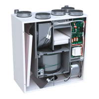
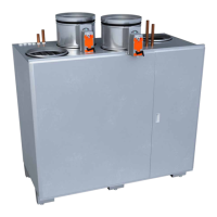
Pinion, Pingvin, Pingvin XL, Pandion,
Pelican, Pegasos and Pegasos XL
Installation location:
Unit Installing location
Pinion, Pingvin, Pingvin
XL and Pandion
On the wall.
Pinion, Pingvin, Pingvin
XL and Pandion
Hanging from the ceiling.
• Requires ceiling installation
plate, (sold as accessory).
Pandion, Pelican,
Pegasos and Pegasos XL
On the oor
• On a suitable at plane.
Installation space:
Unit Installation space
Pinion, Pingvin, Pingvin
XL, Pandion, Pelican,
Pegasos and Pegasos XL
Warm space (over +5°C).
• We recommend the unit is installed in a technical
space.
• Do not install the unit in spaces with high
temperature and high humidity level.
• In certain conditions these can cause
condensation on the unit’s outer shell.
• Consider the unit noise level when choosing the
installation location.
• If possible, install the unit on a soundproof
wall.
• Do not install the ventilation unit directly
outside a bedroom, since even though the
ventilation unit is quiet, it is never completely
silent.
• Install an insulating plate at the back of the
ventilation unit, or otherwise try to prevent
structure borne noise.
• Soft, foamed plastic sheets are recommended
for this (not included in the delivery).
• Make sure that it is possible to connect the
condensate water drain and water lock.
• Consider the space needed for the condensate
water connection.
• Make sure that you install re shuto valves if the
unit is placed in a separate re area.
• Install wall mounted units on a partition wall rather
than on an exterior wall.
• Consider the unit maintenance tasks when
installing the unit.
• Doors of the unit must be fully opened for
maintenance work.
• Leave minimum 15 mm space surrounding the
ventilation unit to the sides. Otherwise, the
service doors cannot be fully opened.
• Consider the space needed for duct coils (if
included).
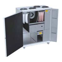
LTR-2, LTR-3, LTR-4, LTR-6, LTR-7 and
LTR-7 XL
Installation location:
Unit Installing location
All LTR-2, LTR-3 and
LTR-4
In two positions:
• Maintenance hatch up.
• Maintenance hatch on the side.
Standard LTR-6, LTR-7
units and LTR-7 XL
Maintenance hatch up.
• On request, units can be made
for installation with the hatch
on the side. This must be
mentioned when the unit is
ordered.
LTR-4, LTR-6, LTR-7
and LTR-7 XL
ventilation units
equipped with built in
cooling coil
We recommend to order with the
maintenance hatch to the side.
• This will enable the
condensation formed in the
cooling coil to drain more easily.
Installation space:
Unit Installation space
LTR-2, LTR-3, LTR-4,
LTR-6, LTR-7 and
LTR-7 XL
Either warm or cold space.
• For example in a storage space
or attic.
CAUTION
CAUTION: Do not install any LTR units so that
the maintenance hatch is facing downwards or
so that the unit is standing upright. Always make
sure that one of the condensate water drain is
downwards.
 Loading...