22
Floor installation
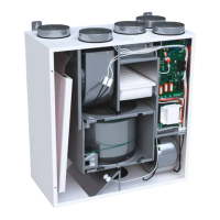
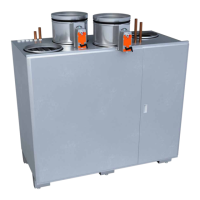
Pandion, Pelican, Pegasos and Pegasos XL
Dimensional drawings for each of the models can be
found at the end of this manual.
To install:
1. Set the ventilation unit on the oor or on the
platform standing on its own rubber feet.
• Make sure there is at least a 10 mm gap all
around the unit.
• If the unit is installed with its side against a
wall, a 15 mm gap is required so the hatch can
be fully opened.
2. Note the space needed for disposing of
condensate water and the water trap under the
unit (if applicable).
• Make sure there is at least 95 cm of space in
front of the unit’s maintenance hatch and
that the electrical connections can be easily
accessed.
3. Connect the unit to a condensate water disposal
drain with water trap.
4. Connect the ducts to the ventilation unit using
rivets.
5. Insulate the ducts according to the instructions in
Insulating ventilation ducts section.
6. Make the applicable electrical and plumbing
connections according to the electrical and
principal diagram at the end of this manual.
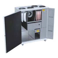
Installing models LTR-2, LTR-3,
LTR-4, LTR-6, LTR-7 and LTR-7 XL
Dimensional drawings for each of the models can be
found at the end of this manual.
Consult the ventilation planner regarding possible
need for additional insulation of the unit if mounted in
a cold space.
If you are using solid (hard) insulation, avoid fastening
the isolation in a way that conducts sound and
vibration to the house frame.
To install:
1. Set the unit on top of an insulating plate.
• For example a chipboard covered with
100mm of hard insulating wool – above the
rafters in the attic or on a separate shelf in a
storage etc.
2. Note the space needed for disposal of condensate
water and the water trap.
• Make sure that there is enough space left in
front of or above the maintenance hatch:
• Tilt the unit slightly in the direction of the
condensation drain.
Unit Free space
LTR-2 and LTR-3 min. 50 cm
LTR-4 and LTR-6 min. 60 cm
LTR-7 and LTR-7 XL min. 70 cm
3. Note the space needed for opening the
maintenance hatch locks.
• Make sure the electrical connections can be
easily accessed.
4. Connect the ducts to the ventilation unit with
circular duct ttings using rivets.
5. Insulate the ducts according to the instructions
in chapter "Insulating ventilation ducts" on page
11.
6. Connect the unit to a condensate water disposal
drain with water trap.
• If the ventilation unit is equipped with a
built-in cooling coil it is recommended to
install the unit with the service hatch to the
side to enable the condensate water to drain
more easily.
• LTR-4 units with cooling coil have two optional
32mm condensation drains. One drain is
welded shut and the other is ready to use.
Depending on the way the LTR-4 unit is
installed, the drain that becomes lower is to
be used. If the lower drain is the welded one,
a short piece of the pipe is sawed o to open
the pipe, and the water trap is connected to
the pipe.
• The unused condensation drain must be
plugged.
7. Make the applicable electrical and plumbing
connections according to the electrical and
principal diagram at the end of this manual.
Installing model eWind W
Principal, control and wiring diagrams for each model
can be found at the end of this manual.
Check the principal charts for units with uid coil. Install
and connect the water pipes according to these charts.
To install:
1. Install the dampers and damper motors.
2. Install and connect the water pipes.
3. Install the valve and the valve actuator.
 Loading...