17Installation instructions
EN
ELECTRICAL CONNECTIONS
DANGER
DANGER: Only an authorized electrician
is allowed to perform electrical work on the
ventilation units.
Refer to the electrical drawings at the end of this
manual.
Preparing for electrical
installations
Before you start the installation, make sure that:
• Appropriate power supply is available for the
ventilation unit.
• At least 30 mA fault current protection is installed.
• Because of this, no other electrical appliances
should be plugged into the same outlet.
• There is appropriate cabling between the unit and
the control panel wall mount.
• The cable must run inside a protective conduit
of at least Ø 20 mm.
• The cable included in the basic delivery is
10m. Optionally a 30 m cable is available.
• The cable heads are type RJ4P4C.
eWind card connections
eWind card connections
NTC sensors
Input Use
TE01 Outdoor temperature measuring TE01.
TE05 Supply air temperature after-heat recovery TE05.
TE10 Supply air temperature TE10
TE32 Exhaust air temperature TE32
TE02 Pre-heated outside air temperature TE02 (CHG/
AGH)
TE45 Return water temperature TE45 (W)
Return water temperature TE46 Option (CG).
Analog inputs AI 0-10V
Analog input AI1 for voltage range 0-10V
Functionality of this input is decided by user. (Parameter
c27)
Input Use
AI1 External CO2 or %RH transmitter
Analog inputs AI7 - AI8 for voltage range 0-5V
Functionality of these inputs are locked by software.
AI7 Extract air humidity RH30
AI8 Extract air temperature TE30
eWind card connections
Analog Outputs AO 0 - 10V
Output Use
AO1 Control voltage for supply fan
AO2 Control voltage for extract fan
AO4 Control voltage for HRW
AO5 Control voltage for heating
AO6 Control voltage for electrical pre-heater. Control
voltage for (CHG). Control voltage for cooler (CG)
Digital outputs DO relays, potential free normally open
contacts.
Output Use
DO2 ON/OFF Control for heating
DO5 ON/OFF Control for dampers
DO8 A/AB alarm output NO (Default)
ON/OFF control for pre-heating (optional)
ON/OFF control for cooling (CG/CHG/AGH)
(optional)
Digital inputs DI (buttons and indications).
Connection to GND only! No voltage allowed to be
connected to digital inputs.
Input Use
DI1 Emergency stop
DI2 External electrical after-heater or pre-heater alarm
DI4 Manual boost
DI5 Away mode. Away mode is active as long as the
input is grounded.
DI6 Fireplace/extractor hood mode. The replace
switch is a momentary push-button switch.
Fireplace mode is active 10 minutes from when
input is grounded. If connected to a changeover
switch, the circuit must be cut for the mode to
reactivate. The extractor hood mode is active
as long as the input is grounded. The selection
between replace mode or extractor hood mode
is done in parameter c12.
DI11 Supply fan tacho input
DI12 Extract fan tacho input
Miscellaneous connections
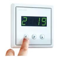
OP1,
OP2
Operating panel connections for eWind
X26 ModBus RTU
24VDC +24VDC
GND GND
 Loading...