2.c Alarm and Warning Display / Indication
2.c.1 Trip Alarm Display
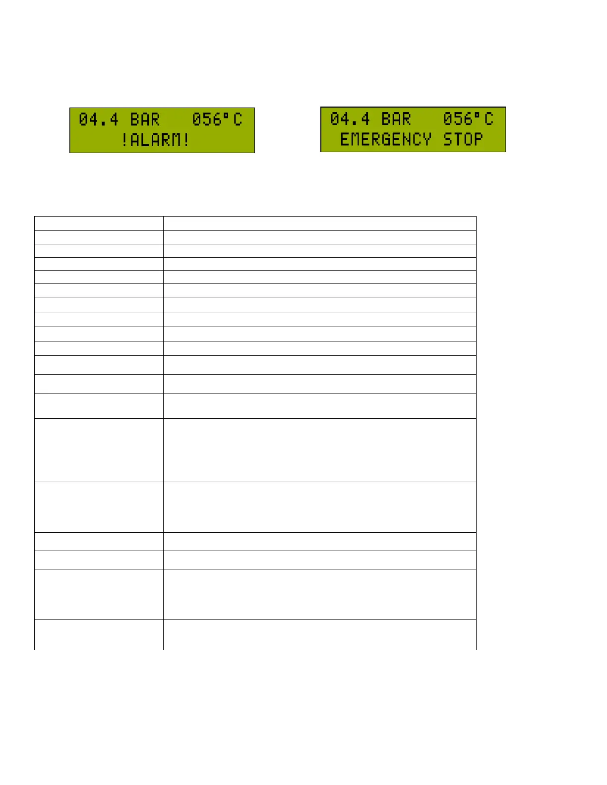
In case of trip alarm, the main motor is stopped. On the below row of the LCD, “!ALARM!” and the alarm code of the last
alarm blink every 1 second alternatingly. Even if the fault condition is not active any more, the trip alarm is kept being
displayed. When the alarm is reset, the alarm on the screen is cleared. Previous alarms may be seen in the alarm record.
Line Pressure Sensor not connected or faulty (AN-1)
Screw Pressure Sensor not connected or faulty (AN-2)
Temperature Sensor not connected or faulty (AN-0)
Line Pressure >= “P4.1.1 Pressure High Limit”
Screw Temperature <= ”P4.2.2 Temperature Low Limit”
There is a short-circuit between +12V and GND line on the sockets.
Max. Start/Stop count in
an Hour
Number of Start/Stop in an Hour >= ”P4.3.6 Maximum Start/Stop”
When digital input IN-5 function is selected as Remote Load, this
input functions as Remote Load Input. If the function is set to
anything else other than Remote Control, this input functions as an
auxiliary alarm input. Also this input can be assigned as Screw
Pressure Switch or Line Pressure Switch.
If "P4.5.2-Start/Stop Control Source” is selected as Remote control ,
digital input IN-6 is used for remote start. If it is not selected as
remote start, IN-6 is used as auxiliary failure input.
Screw Pressure >= “P4.1.4 Screw Pressure Alarm”
Screw Pressure – Line Pressure >= “P4.1.6 Pressure Diff. Alarm”
If the Screw Pressure > “P4.1.8 Screw Pressure Start Value” during
the initial start this alarm is indicated. If the screw pressure drops
below this value the alarm is automatically acknowledged and the
compressor will start.
If the IN5 digital input is set as Screw Pressure Switch, when the
compressor tries to start and this input is active than the alarm is
signaled. When the IN5 is de-activated the alarm will be removed.