22
Marcare la maglia di aggancio della
catena così da avere, per successive
installazioni, l’attrezzatura sempre alla
stessa altezza operativa.
Togliere il piede dalla posizione di
appoggio, sfilando la coppiglia a R (A -
fig.C6), inserirlo rovesciato nella sua
sede (posizione di lavoro) e bloccare con
la coppiglia a R.
Continuare l’installazione in base al
modello di attrezzatura in vostro
possesso.
Modelli meccanici: inserire la piastra
forata nel perno del braccio sinistro del
trattore (A - fig.C7). - Inserire la catena di
controllo barra di taglio (B - fig.C7) nel
foro posteriore della piastra e bloccarla
inserendo una sua maglia nell’apposita
asola sulla piastra. - Agendo sulla leva in cabina,
sollevare il sollevatore e verificare che raggiunta una
altezza prestabilita (la slitta a circa 15 cm da terra -
fig.C8) con l’attrezzatura si solleva anche la barra di
taglio. - Regolare opportunamente la catena,
scegliendo una maglia diversa da quella
precedentemente impegnata, se tale condizione è
anticipata oppure posticipata.
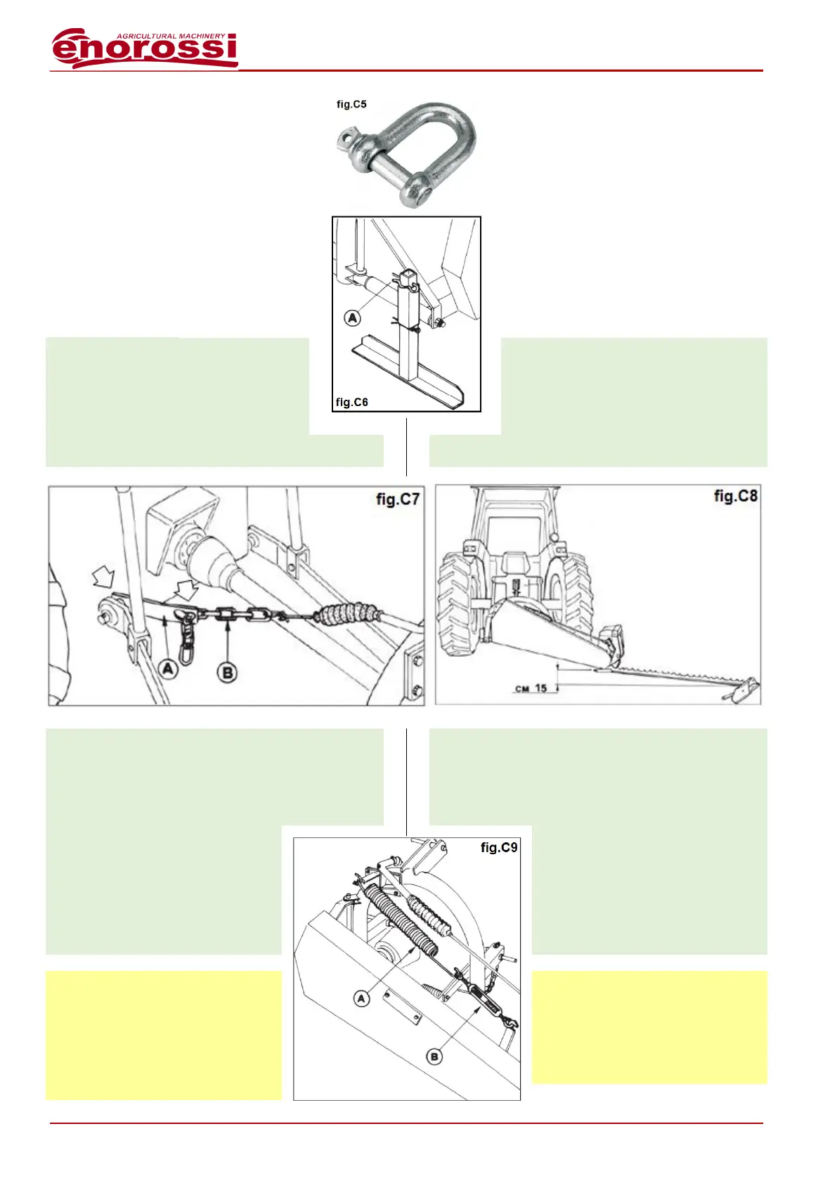
Nota: per l’aggancio della catena, in
alternativa, utilizzare il cavallotto
(fig.C5) (in dotazione).
Marcare la maglia di aggancio della
catena così da avere, per successive
installazioni, l’attrezzatura sempre
alla stessa altezza operativa.
IMPORTANTE
Il peso della barra falciante che
grava sul terreno viene ammortizzato
dalla molla A (fig.C9) la cui tensione
viene regolata dal tenditore B
(fig.C9). Questo dispositivo è
presente anche sui modelli idraulici
dell’attrezzatura.
Mark the chain hooking mail in order to
have, for subsequent installations, the
equipment always at the same operating
height.
Remove the foot from the parking position
by pulling out the R cotter pin (A - fig.C6),
insert the foot in its housing in overturned
position (working position) and lock by R
cotter pin.
To continue the installation in base to the
equipment model in your possession.
Mechanical models: insert the holed
plate in the pin of tractor left arm (A -
fig.C7). - To insert the check chain of
cutting bar (B - fig.C7) in the rear hole of
the plate and lock it by inserting one its
mail in the special eyelet on the plate. -
By acting on the lever in the cabin, to lift the hydraulic
lift and to verify that when a pre-arranged height is
reached (the slide to around 15 cm from ground -
fig.C8) with the equipment the cutting bar lifts too. - If
such condition is anticipated or postponed, to
opportunely adjust the chain, by choosing a different
mail from the one previously used.
Note: to hook the chain to tractor, it
is possible use in alternative the U
bolt (supplied by us) (fig.C5).
Mark the chain hooking mail in order
to have, for subsequent installations,
the equipment always at the same
operating height.
IMPORTANT
The weight of sickle bar mower on
ground is absorbed by compensation
spring A (fig.C9) whose stretch can
be adjusted by turnbuckle B (fig.C9).
This component is also mounted on
hydraulic models of equipment.