28
ATTENZIONE: la regolazione, che potrebbe interes-
sare entrambe le valvole, deve essere eseguita su
una per volta. NON AGIRE CONTEMPORANEA-
MENTE SU ENTRAMBE LE VALVOLE.
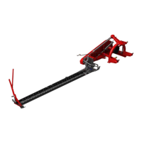
Per intervenire su una
valvola, agire come
segue:
allentare la ghiera
di blocco 1;
ruotare la valvola
nel senso –
(meno) fino a fine
corsa;
ruotare la valvola
nel senso + (più)
di mezzo giro per
volta e, di volta in
volta, effettuare un
controllo operativo
della funzione,
agendo sulla
corrispondente
leva in cabina;
quando l’esecuzione risulta soddisfacente,
avvitare la ghiera 1 fino a bloccare la valvola;
se necessario, ripetere la stessa procedura
sull’altra valvola.
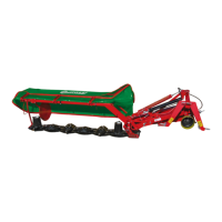
Controllo e Regolazione tensione cinghie di
trasmissione
Controllo: verificare periodicamente la tensione delle
cinghie per evitare un loro slittamento.
- Svitare, senza rimuoverli, i due dadi di fissaggio
(G1 - fig. D10) della piastrina di ispezione;
- Ruotare verso l’alto la piastrina per accedere alla
cinghia G;
- Tastare la cinghia G2, verificare che l’escursione
resti tra 0,6 e 10 mm.
Ripristino: per aumentare la tensione alle cinghie
(+), avvitare il dado A (fig.D11). Per diminuire la
tensione (--) alle cinghie, svitare il dado A;
WARNING: the adjustment, which should affect both
the valves, must be performed on one at the time.
DO NOT ACT ON BOTH THE VALVES AT THE
SAME TIME.
For adjust a valve,
act as follows:
loosen locking
ring nut 1;
rotate the valve in
– (less) direction
until to stop point;
rotate the valve in
+ (more) direction
of half lap at the
time and, time by
time, to perform
an operational
test of the
function, by
acting on the
corresponding
lever in cabin;
when the test results satisfactory, to screw the
ring nut 1 until that the valve results locked;
if necessary, repeat the same procedure on the
other valve.
Check and adjustment of belt tension
Check: to periodically verify the tension of the belts
to avoid a slipping of them.
- Unscrew, without removing them, two fixing nuts
(G1 - fig. D10) of the inspection plate;
- Rotate upward the plate to access to the belt G;
- Touch the belt G2, to verify that the excursion
stays between 0,6 and 10 mm.
Reactivation: to increase the tension to the belts (+),
to screw the nut A (fig.D11). To decrease the tension
(--) to the belts, to unscrew the nut A;
Prima di iniziare il lavoro
verificare la tensione
delle cinghie
check belts tension
before working operation