27
- Modelli meccanici: in cabina, agendo sulla leva
del sollevatore idraulico, sollevare la barra di
taglio fino a che la leva di controllo E (fig. D7)
tocca il suo punto di battuta F;
- In cabina, agendo sulla leva di movimentazione
del martinetto, sollevare la barra di taglio di circa
30° dal suolo, come in fig.D7. Questo comporterà
anche il sollevamento, seppur di poco, di tutta la
macchina dal suolo che comunque è sufficiente
per effettuare in sicurezza il cambio di direzione.
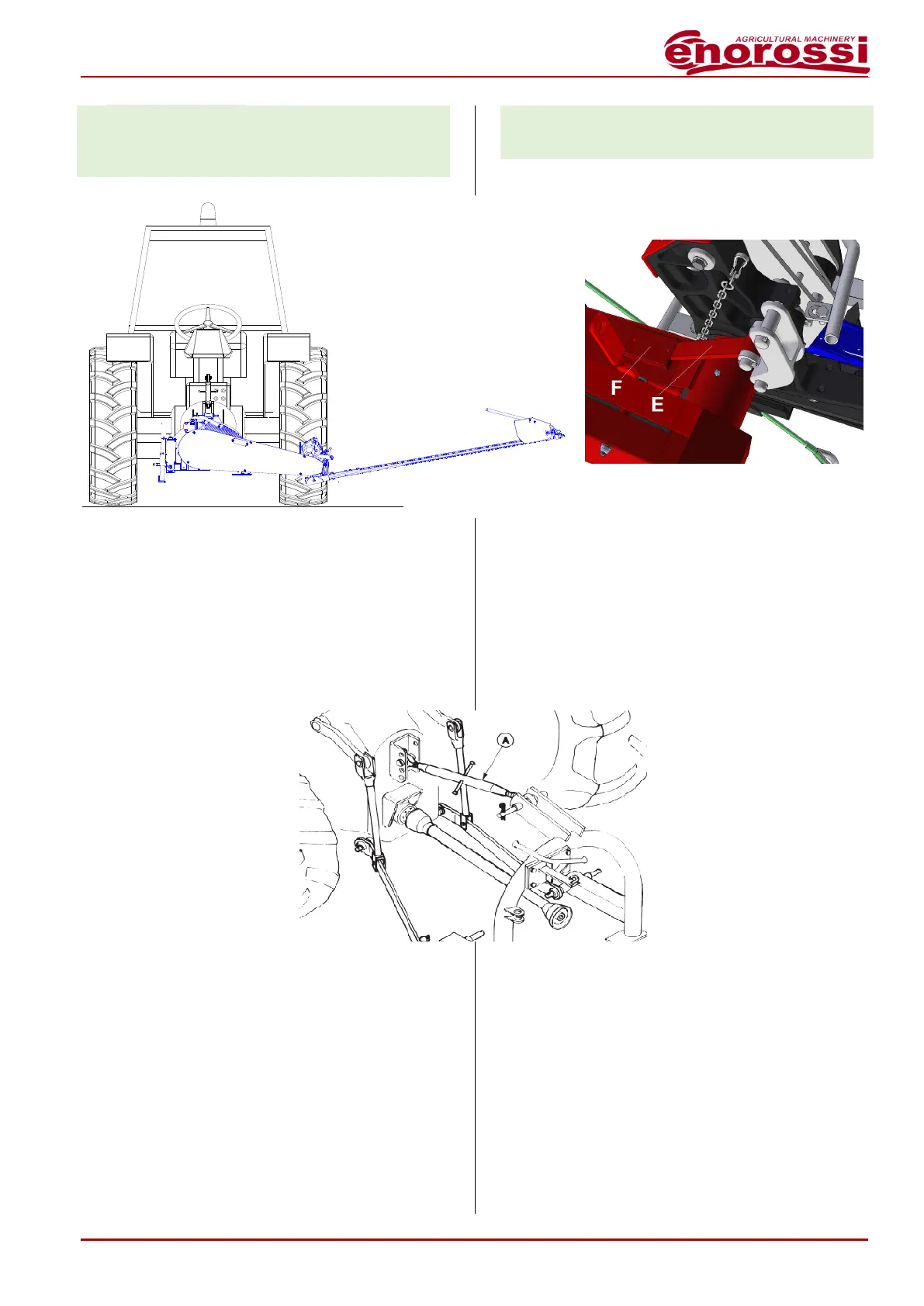
Regolazione dell’altezza di taglio
La regolazione si ottiene
modificando l’inclinazione
della barra di taglio, rispetto
alla direzione di
avanzamento del trattore.
Mettere la barra di taglio in
piano sul terreno e poi agire
sul tirante registrabile del
terzo punto A (fig.D8)
variando la sua lunghezza.
Sul tirante, allentare il
controdado, poi svitare o
avvitare il suo corpo e, una
volta eseguita la regolazione, stringere il controdado
L’altezza minima comunque non deve essere
inferiore a 20÷30 mm.
Regolazione velocità abbassamento/sollevamen-
to della barra di taglio
Nel caso in cui l’esecuzione di una delle due funzioni,
oppure di entrambe risultasse troppo veloce o troppo
lenta allora sarà necessario agire sulle apposite
valvole di regolazione di flusso (A per il
sollevamento e B per l’abbassamento), montate
contrapposte sulla relativa tubazione.
- Mechanical models: in cabin, by handling the
hydraulic lift lever, lift the cutting bar until E
control lever (fig. D7) touches its stop point (F);
- In cabin, by handling the lever of moving of the
cylinder, lift cutting the bar of around 30° from the
ground, as in fig.D7. This will also involve the
lifting, even slightly, of the whole equipment from
the ground that it is however enough to effect the
change of direction in safety.
Adjustment of cutting height
The adjustment is obtained
by changing the tilt of the
cutting bar, in comparison to
the advancement direction of
the tractor.
Put the cutting in plain on the
ground and then act on the
adjustable tie-rod of third
point A (fig.D8) by varying its
length.
On tie-rod, loosen the lock
nut, then unscrew or screw
its body and, a time the
adjustment is performed, tighten the lock nut.
However, the minimum height must not be less
than 20÷30 mm.
Adjustment of the lowering/lifting speed of the
cutting bar
If the operating of one of two functions, or of both,
should results very fast or very slow in that case will
be necessary to act on the special flow regulating
valves (A for the lifting and B for the lowering),
installed counterposed on the related hose.