22
IQ System Controller 3/3G Quick Install Guide
AWG TORQUE (LB.IN)
14 -10 25
8 30
4 - 6 35
2 - 3 40
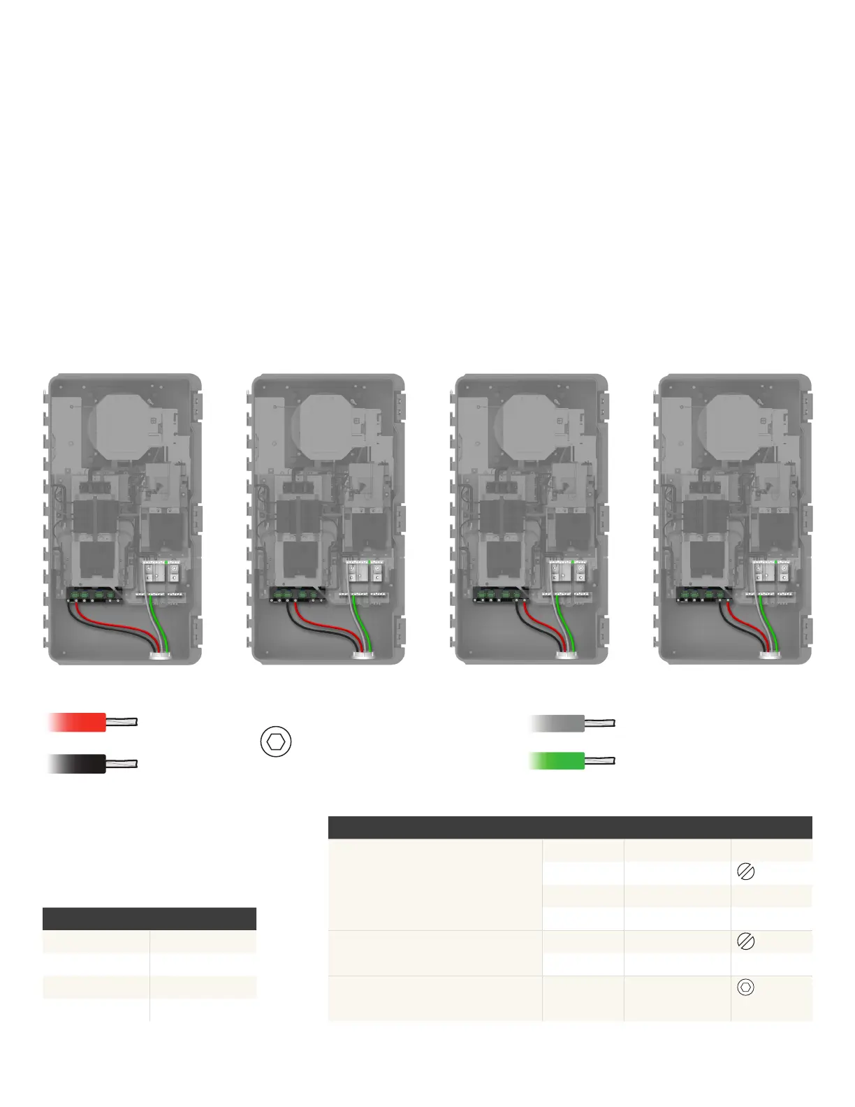
IQ Battery wiring
PV/IQ Battery/Generator connections
IQ System Controller 3G:
generator wiring
IQ System Controller 3:
additional IQ Battery
wiringPV wiring
Connect the DER (IQ Battery, IQ Combiner/Solar and generator)
wires to the lugs at the bottom as indicated in the following images.
Refer to the wiring table and torque recommendation before
connecting the wires. Refer to local codes for any specic local
requirements.
1/8" 2-14 AWG
DER wiring
Section C - Wiring
NEUTRAL AND GROUND CONNECTIONS AWG TORQUE (LB.IN)
Neutral and ground bar – large holes
1/0 - 3 50
4 - 6 45
8 40
10 - 14 35
Neutral and ground bar – small holes
6 - 8 25
10 - 14 15
Neutral lugs 300 kcmil - 6 275
3/8"
5/16"-24 UNF
#10-32 UNF
1/0-14 AWG
300 kcmil-14 AWG