28
IQ System Controller 3/3G Quick Install Guide
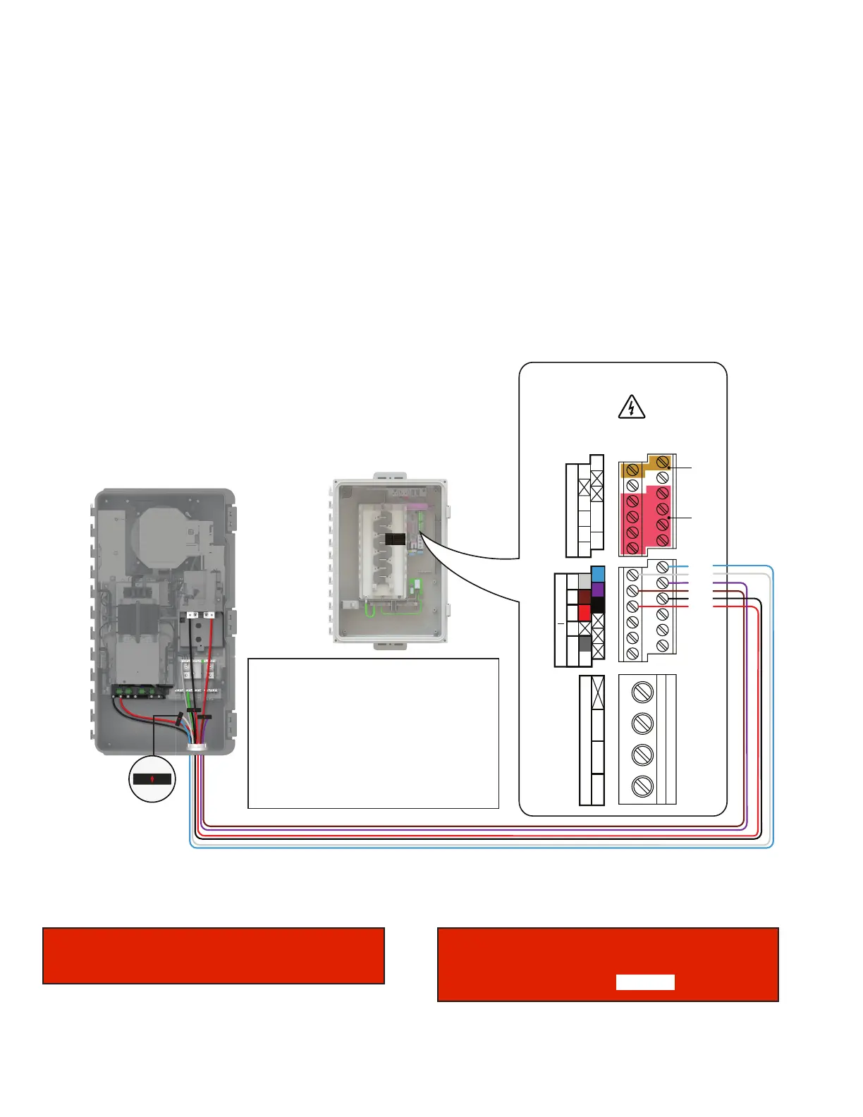
IQ Gateway Terminal Block
Not used
Red
Black
Brown
Purple
White
Blue
Relay contacts
(if needed)
CU, C, AWG MIN
MEAS CAT III
OVC III
PD, B
OVC II
NLL
P
Production
Digital Input
1234 NO
REF CCommon
Relay
Consumption
C C C
If PCS is being used, place the following label on the dead front with
the PCS setting lled in the blank space.
When installing a generator, the generator CTs should be paralleled
to the consumption CTs wiring using a Wago nut.
CT wiring
Section C - Wiring
There are multiple scenarios for CT wiring. For a complete
description, please refer to IQ Gateway QIG.
Place the consumption CTs as shown below for:
• Whole home backup
• Partial home backup with Power Control Systems (PCS) for
Main Panel Upgrade (MPU) avoidance
• Any system with generator integration
For PCS setup, refer to the Enphase Installer App.
If using PCS - after placing the consumption CTs and wiring to
the IQ Gateway, the following label has to be pasted on the CTs.
Battery CT is placed on L2 wire from IQ Battery.
Consumption CTs are placed on L1 and L2 main
wiring to IQ System Controller.
For partial home backup systems without
generator integration and without PCS for MPU
avoidance place the CTs on L1 and L2 between
the meter and the main panel.
If using CT-200-SPLIT ensure the CT has
“Service Entrance Rated” label on it.
Battery CT
orientation
This sensor is part of a Power Control System. Do not remove
or disable. Replace with same type and rating.
THE MAXIMUM CURRENT BACKFED BY THIS SYSTEM TO THE MAIN PANEL MAY BE
CONTRTOLLED ELECTRONICALLY. REFER TO MANUFACTURER’S INSTRUCTIONS
FOR MORE INFORMATION
PCS CONTROLLED CURRENT SETTINGS: AMPS