32
IQ System Controller 3/3G Quick Install Guide
Section C - Wiring
Here is a table providing termination resistor locations for the above
sequences:
CONTROL WIRING SEQUENCE TERMINATION RESISTOR LOCATION
IQ Combiner 5/5C → IQ System Controller 3G → IQ Battery(s) 5P
• IQ Combiner 5/5C
• Last IQ Battery 5P in the daisy chain
IQ Combiner 5/5C → IQ System Controller 3 → IQ Battery(s) 5P
• IQ Combiner 5/5C
• Last IQ Battery 5P in the daisy chain
IQ Combiner 5/5C → IQ Battery(s) 5P → IQ System Controller 3/3G
• IQ Combiner 5/5C
• IQ System Controller 3/3G
IQ System Controller 3/3G → IQ Combiner 5/5C → IQ Battery(s) 5P
• IQ System Controller 3/3G
• Last IQ Battery 5P in the daisy chain
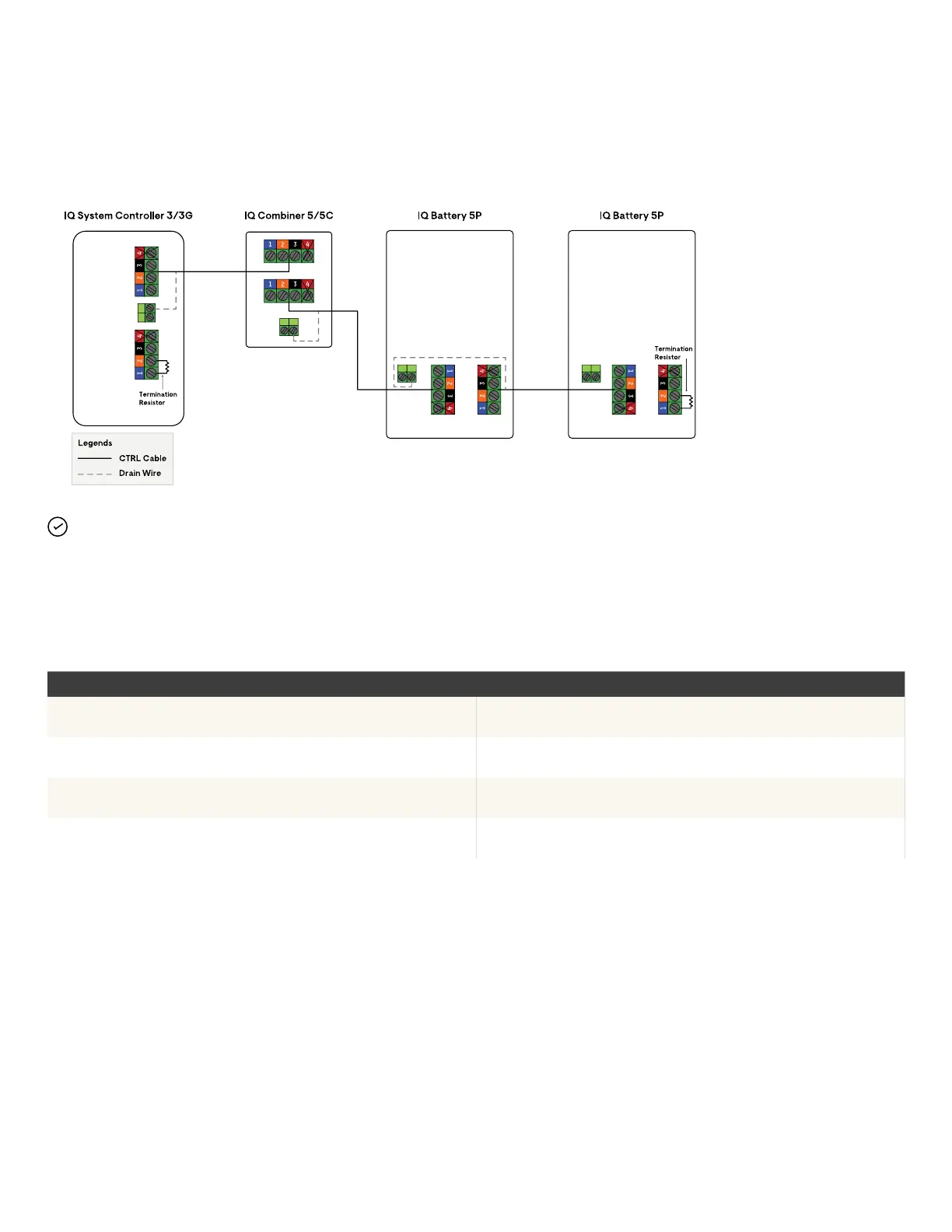
Sequence 3: IQ System Controller 3/3G → IQ Combiner 5/5C → IQ Battery(s) 5P
NOTE: Total length of CTRL wiring across the system cannot
exceed 250 feet to ensure the system operates as per
specications.