Mounting the 8 Port Switches
Enterasys 800-Series Hardware Installation Guide 2-15
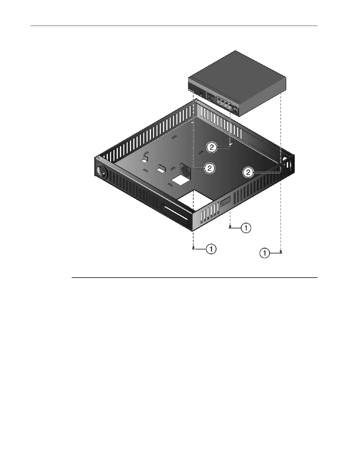
Figure 2-11 Installing the Switch in the 08G20G2-08 or 08G20G2-08P Lockbox Tray
2. Mount the switch inside the lockbox tray in the direction shown in Figure 2-11 on page 2-15,
aligning the three screw holes on the bottom of the unit with the three holes in the lockbox
tray.
3. Using the screws provided, fasten the switch to the lockbox tray.
Installing the Optional Redundant Power Supply
Once the switch is secured in the lockbox tray, assemble the rest of the 08G20G2-08 or
08G20G2-08P components into the lockbox.
To install an optional power supply into the lockbox:
1. Using one of the hook & loop straps provided, complete the following steps to secure one end
of the power supply in the position shown in Figure 2-12 on page 2-16:
1 Mounting screws (three) 2 Mounting screw holes
 Loading...