Mounting the 8 Port Switches
Enterasys 800-Series Hardware Installation Guide 2-19
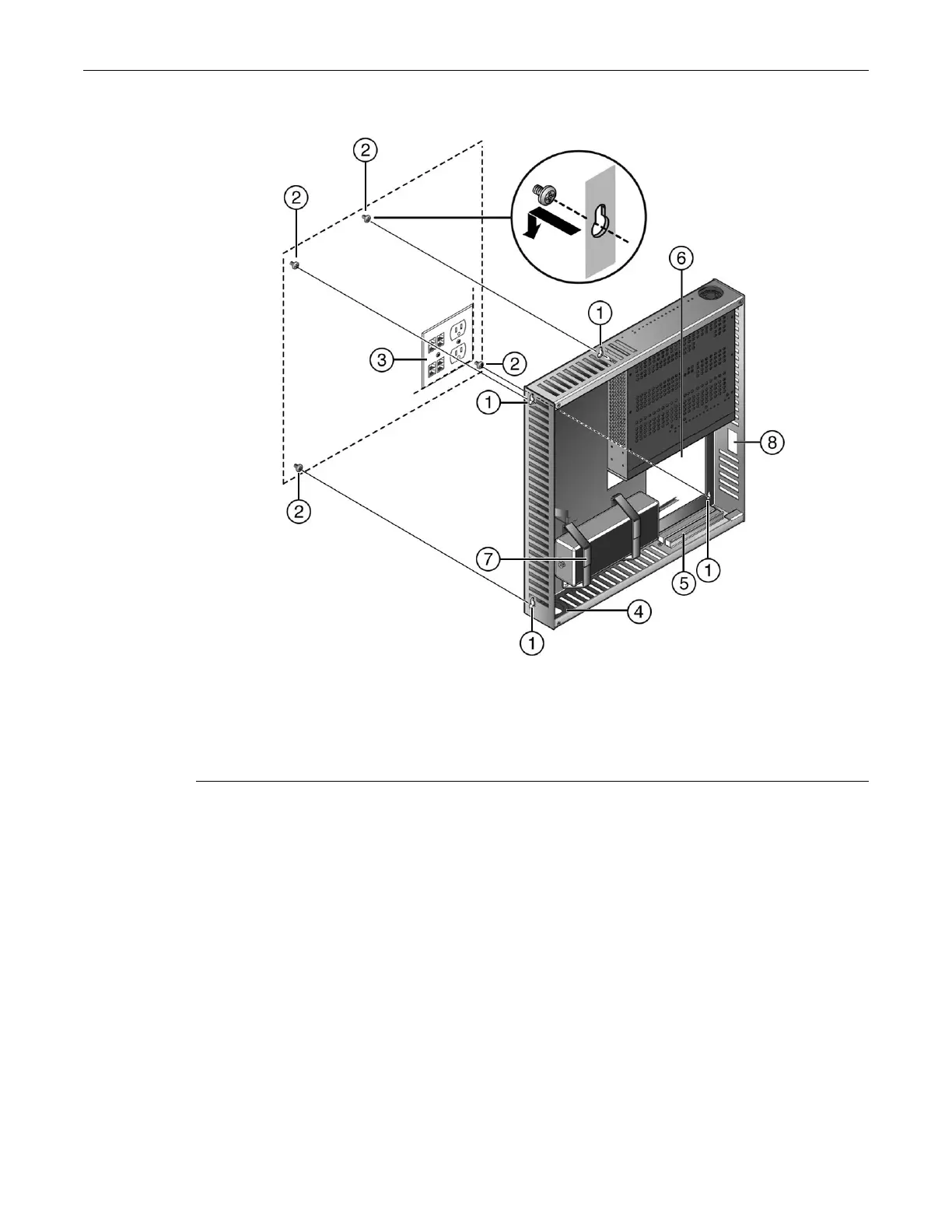
Figure 2-15 Mounting the Lockbox Over an AC Power/Data Outlet
2. Position the lockbox screw holes over the installed wall screws.
3. Secure the assembled lockbox in place by pulling slightly downward on the unit.
Attaching and Locking the Cover
Once the switch and power supplies are assembled in the lockbox tray, and power and network
cabling is connected, refer to Figure 2-16 on page 2-20 and proceed to attach and lock the cover as
follows:
1 Wall mounting screw holes (four) 5 Network wire relief bracket (shown installed)
2 Wall mounting screws (not provided) 6 AC power/data outlet opening
3 AC power/data outlet 7 Power supply hook & loop strap
4 AC cord opening (for mounting away from
outlet)
8 Fiber adapter opening
 Loading...