Installing and Removing an IOM
2-12 Installation
3. Unpackthemodulebytakingitfromitsshippingboxandremovinganypackagingmaterials,
andremovingthemodulefromitsprotectiveplasticbag.(Savetheshippingboxandmaterials
intheeventtheunitmustbereshipped.)
4. Examinethemodulecarefully,checkingfordamage.Ifanydamageisfound,do
notinstallit.
ContactEnterasys Networksforinstructions.
5. Removethecoverplatefromaslotbylooseningthecoverplate’stwocaptivescrews.
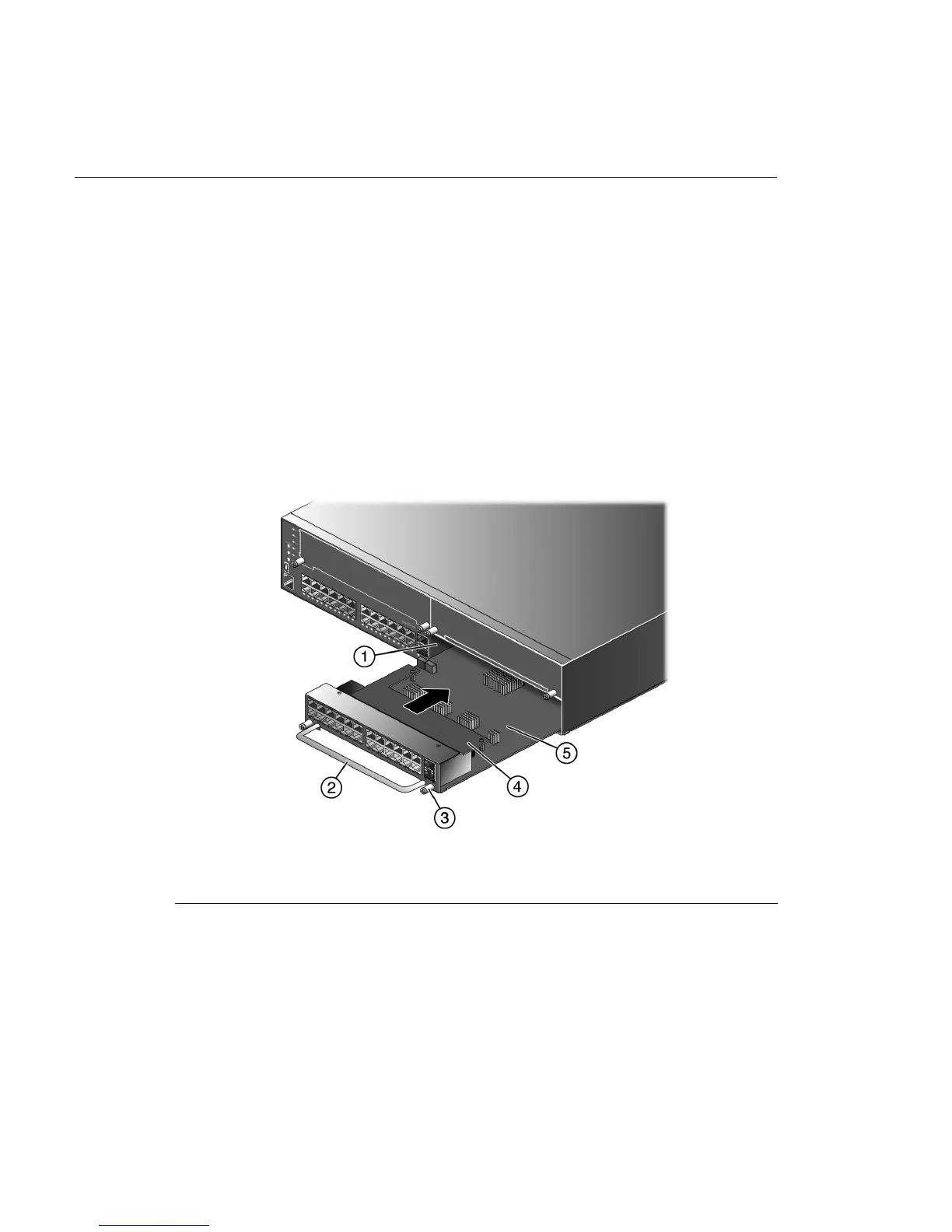
6. InserttheIOMintheguiderailoftheslot.Gentlyslidethemoduleintotheslot,asshownin
Figure 2‐4,untiltheIOMengagestheconnectoronthebackplane
andisflushwithadjoining
coverplates.
Oncetheconnectionismade,theslot’sstatusLEDflashesgreenandIOMinitializationbegins.
TheIOMinitializationlastsforapproximatelythirtysecondstoallowenoughtimetotighten
theIOM’scaptivescrews.Wheninitializationiscompletetheslot’sstatusLEDturnssolid
greenand
theIOMisreadyforuse.
Figure 2-4 Installing an IOM (G3G-24TX with optional PoE shown)
7. Ifyouareinstallingadditionalmodules,waituntiltheslotstatusLEDforthepreviously
installedIOMissolidgreenbeforerepeatingthisproceduretoinstalladditionalmodules.
Savecoverplatesforoptionalfutureuse.
8. Aftercompletingallmoduleinstallations,besuretoinstallcoverplate(s)
overanyunused
IOMslot(s)tocontainEMIradiationandensureproperaircirculation.
IOM Initialization Behavior
TheIOMconfigurationissetduringtheIOM’sinitialization.WhenyouinstallanIOMintoaslot
thathasnotpreviouslyhadanIOMinstalled,thedefaultconfigurationwillbeappliedtoallports
ontheIOM.
1 IOM slot 2 4 Optional PoE module
2 IOM handle 5 IOM
3 Captive screw

 Loading...


