Connecting to the Network
Enterasys G-Series Hardware Installation Guide 2-17
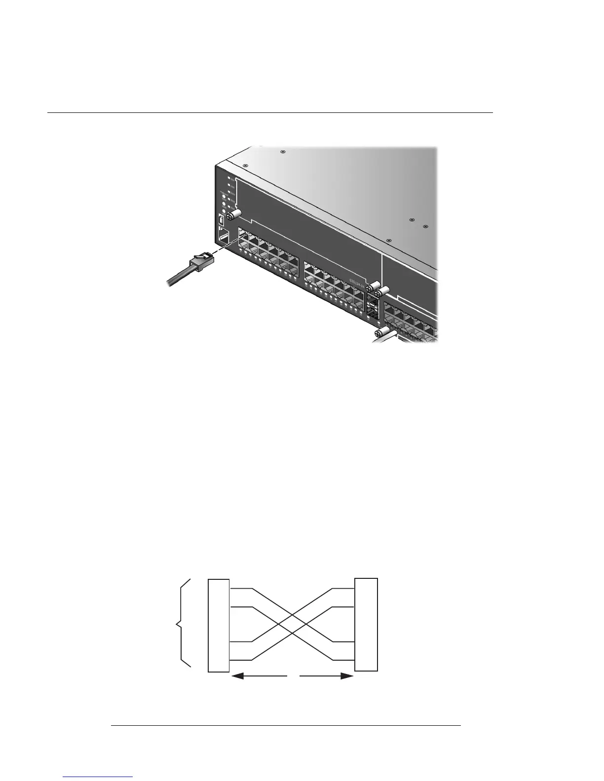
Figure 2-5 Connecting a UTP Cable Segment to RJ45 Port
3. VerifythatalinkexistsbycheckingthattheLink/ActivityLEDison(solidgreenorblinking
green).IftheLink/Act ivityLEDisoff,performthefollowingstepsuntilitison:
a. VerifythatthecablingbeingusedisCategory 5orbetterwithanimpedancebetween85
and111 ohmswitha
maximumlengthof100meters(328feet).
b. Verifythatthedeviceatthe otherendofthetwistedpairsegmentisonandproperly
connectedtothesegment.
c. VerifythattheRJ45connectorsonthetwistedpairsegmenthavetheproperpinoutsand
checkthecableforcontinuity.Typically,acrossover
cableisusedbetweenhubdevices.A
straight‐throughcableisusedtoconnectbetweenG‐Seriesorhubdevicesandanenduser
(computer).RefertoFigure 2‐6andFigure 2‐7onpage 2‐18forfour‐wireRJ45
connections.RefertoFigure 2‐8andFigure 2‐9onpage 2‐19
foreight‐wireRJ45
connections.
4. Ifalinkisnotestablished,contactEnterasys Networks.Referto“GettingHelp”onpage xvii
fordetails.
Repeatallstepsaboveuntilallconnectionshavebeenmade.
Figure 2-6 Four-Wire Crossover Cable RJ45 Pinouts for 10/100BASE-TX
1 RJ45 switch port 3 RJ45-to-RJ45 crossover cable
2 Other device port 4 RX+/RX- and TX+/TX-connections
These connections must share a common color pair.
TX+
TX
RX+
RX 2
1
3
6
TX+
TX
2
1
3
6
RX+
RX
ÀÁ
Â
Ã

 Loading...


