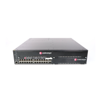
Completing the Installation
2-22 Installation
2. InsertthecableconnectorintotheSFP/XFPconnectoruntilitclicksintoplace.
Figure 2-11 Cable Connection (LC shown) to Uplink Port with SFP/XFP Installed
3. Plugtheotherendofthecableintotheappropriateportontheotherdevice.Somecablesmay
beterminatedattheotherendwithtwoseparateconnectors,oneforeachfiber‐opticstrand.In
thiscase,ensurethatthetransmitfiber‐opticstrandfrom
theG‐Seriesisconnectedtothe
receiveportoftheotherdevice,andthereceivefiber‐opticstrandontheG‐Seriesisconnected
tothetransmitportoftheotherdevice.
4. RepeatthisprocedureforotherSFP/XFPports,ifneeded.
5. IfanSFP/XFPportisunused,installadust
cover.
Completing the Installation
1. Powerontheswitch.
2. VerifythatthePWR1andPWR2powerLEDsarelit.Referto“PowerLEDDisplays”on
page 2‐14forinformationoninterpretingthepowerLEDs.
3. VerifythattheSYSTEMLEDblinksinitiallythenbecomessolidgreen.
4. Makesurethatthenetworkdevicesconnectedtotheswitchports
arepoweredon,thenverify
thateachLink/ActivityLEDisON(solidgreenorblinkinggreen).
5. Atthedeviceconnectedtotheconsoleport,performthefollowing:
a. EnteradminforUsername.
b. AtthePasswordprompt,pressENTER(RETURN).
Note: Leave the protective covers in place when the connectors are not in use to prevent
contamination.
1 Combo SFP port with MGBIC installed 2 LC cable connector 3 Release tab

 Loading...