Connecting to the Console Port
Enterasys G-Series Hardware Installation Guide 2-15
Toconnecttotheconsoleport:
1. ConnecttheRJ45connectoratoneendofthecabletotheRJ45consoleportontheG‐Series
switch.
2. PlugtheRJ45connectorattheotherendofthecableintotheRJ45toDB9adapter.
3. ConnecttheRJ45toDB9adaptertotheserial
portonaterminaloraPCrunningterminal
emulationsoftware.
4. Makesuretheterminalemulationsoftwareissetasfollows:
–Selecttheappropriateserialport(COMport1or2).
–Setthedatarateto9600baud.
–Setthedataformatto8databits,1stopbit,andnoparity.
–Set
flowcontroltonone.
–SettheemulationmodetoVT100.
–WhenusingHyperTerminal,selectTerm inal keys,notWindowskeys.
5. WhenyouarereadytobeginconfiguringtheG‐SeriesEthernetswitch,usetheproceduresin
“CompletingtheInstallation”onpage 2‐22topowerontheswitchandbootthesoftware.You
willperforminitialsetupbyenteringCLIcommandsonthemanagementconsole.
ForadescriptionofhowtousetheCLIanddescriptionsofalltheCLIcommands,refertothe
EnterasysG‐SeriesCLIReference.
Table 2-2 Console Port Pinout
Pin Connection
1TXD
2 Unused
3 Unused
4RXD
5GND
6 Unused
7 Unused
8 Unused
Table 2-3 RJ45 to DB9 Adapter Pinout
Signal RJ45 Pin DB9 Pin
Receive (RX) 1 2
Transmit (TX) 4 3
Ground (GRD) 5 5
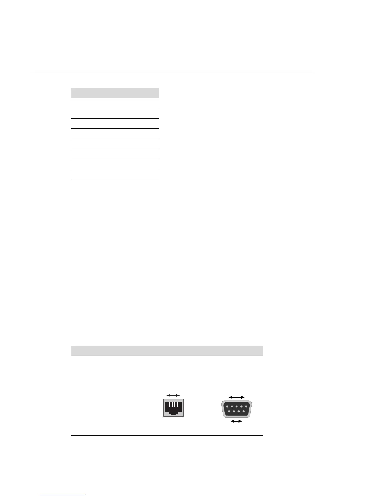
RJ45 Connector (Female)
81
Pins
DB9 Connector (Female

 Loading...


