37
IP2045EN - 2014-09-22
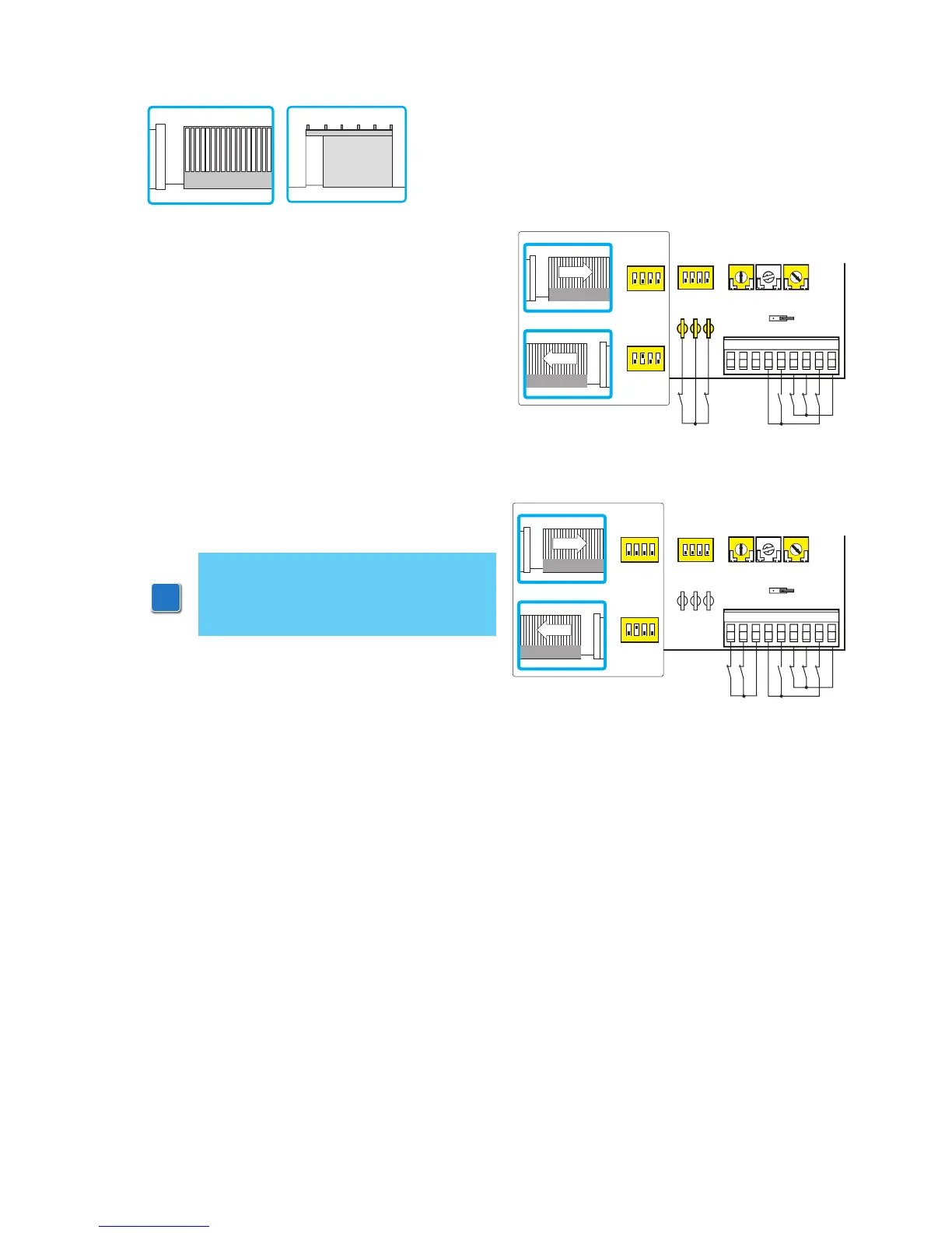
(Example 1). Connect opening and closing limit
switches N.C. contacts to plug 12-0-11;
or
(Example 2). Connect opening and closing limit
switches N.C. contacts to terminals 0-11-12.
With the above connections, when limit switches
operate the wing stops.
In the event of obstacle detection, the wing stops
and releases during opening operation and reo-
pens during closing operation.
NOTE: if the self-controlled safety edge
SOFA1-SOFA2 is used, make the con-
nections indicated in par. 4.1.
R1
<MAXMAX
TC TM
JR6
12
12 011
11 01568941
1
ON
234
Limit switch
Limit switch
DIP2=OFF
DIP2=ON
1
ON
234
1
ON
234
R1
<MAXMAX
TC TM
JR6
12
12 011
11 01568941
1
ON
234
Limit switch
Limit switch
DIP2=OFF
DIP2=ON
1
ON
234
1
ON
234
10. Example applications for sliding door and gates
When control panel is used for sliding automations ope-
rations:
- set JR6=OFF;
- set TM=MAX;
- select the proper opening direction by means of DIP2.