Shenzhen Envicool Technology Co., Ltd.
consult the air conditioning equipment company. If you need to install a solenoid
valve, but it is not installed inside the air-conditioning equipment when leaving the
factory, please find the solenoid valve to be installed in the delivery accessories. If you
do not find it, please contact the air-conditioning equipment company.
5. When welding the solenoid valve, please pay attention to wrap a damp cloth.
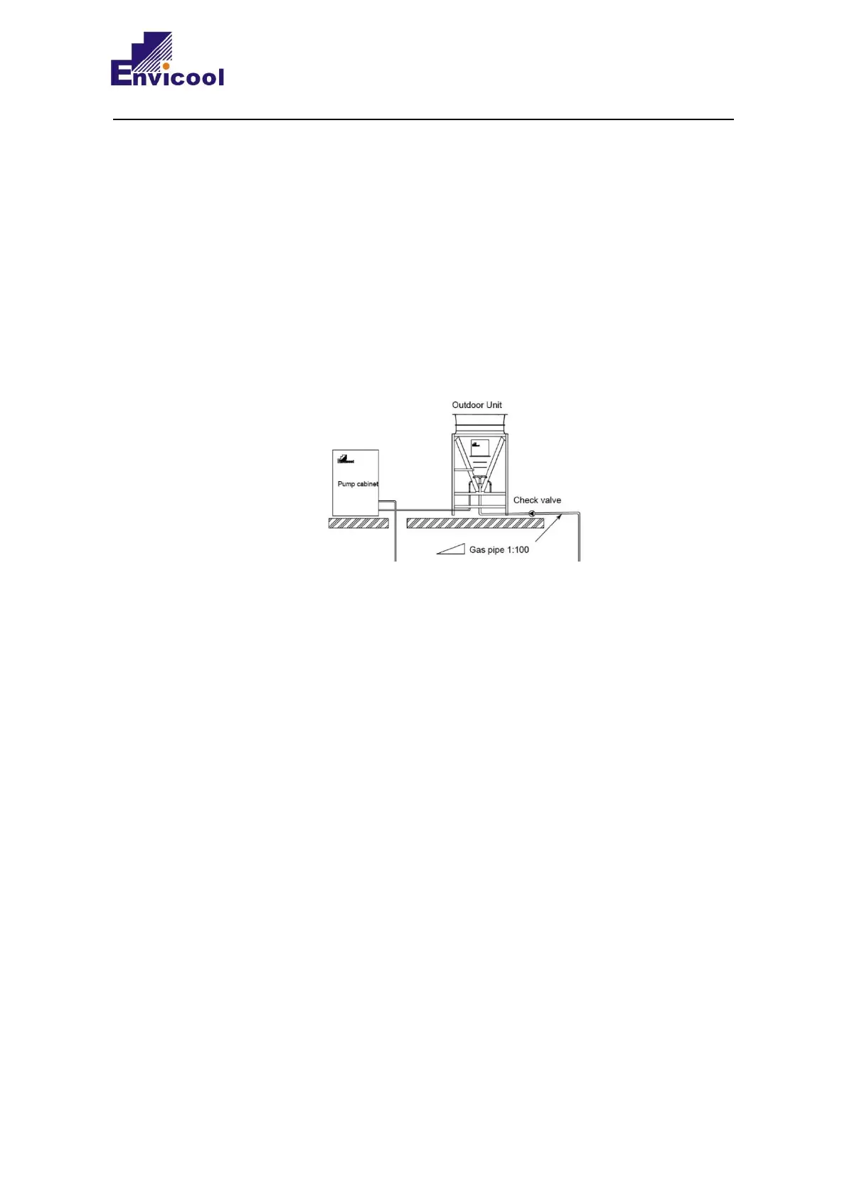
6. The installation height of the bottom of the pump cabinet should be as low as possible or
the same as the installation height of the external machine, and should not be higher
than the installation height of the bottom of the condenser, to avoid the refrigerant in
the liquid storage tank from flowing into the condenser. The schematic diagram is as
follows (see Figure 2-18 for the complete installation diagram):
7. In order to ensure smooth oil return from the compressor, the horizontal air side pipeline
should have an inclination of 1:100 in the direction away from the compressor. The
proximal end is 10mm lower.
8. The outdoor unit is higher than the indoor unit, and the vertical height H1 should not
exceed 30m; the outdoor unit is lower than the indoor unit, and the vertical height H2
should not exceed 10m. If you have special needs, please consult the equipment
manufacturer. The air-conditioning equipment company will not bear any
responsibility for equipment damage caused by non-compliance with the construction
specifications required by the equipment manufacturer!
9. When the total length of the pipeline exceeds 50m, the engineering pipe liquid pipe
needs to add a bypass filter assembly to prevent excessive impurities such as oxide
scale in the pipeline during startup and commissioning, which may cause blockage of
the dryer filter inside the unit. The bypass filter assembly should be installed in the
engineering liquid pipe, near the inlet of the indoor unit liquid pipe. The schematic
diagram of the bypass filter is as follows: