Shenzhen Envicool Technology Co., Ltd.
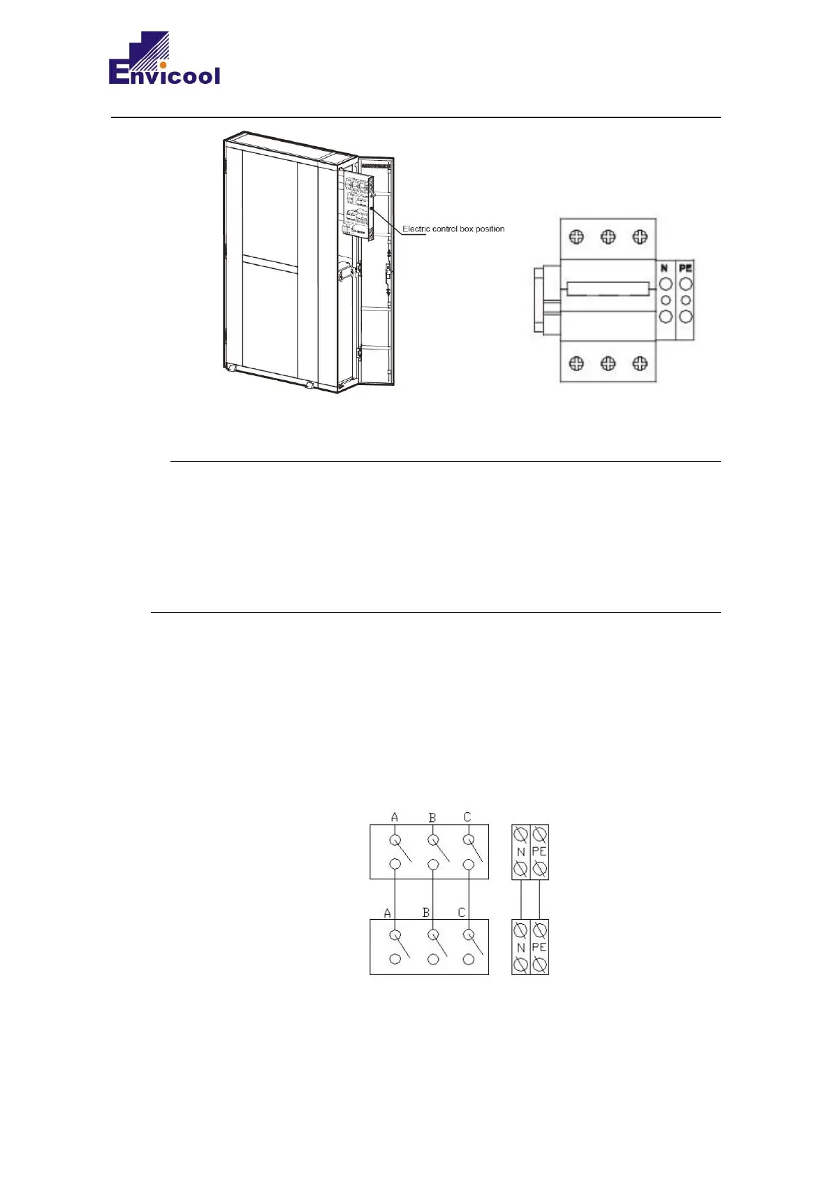
Fig. 2-24 Schematic diagram of the electrical connection of the indoor unit
1、 The electric control box of XR023A is drawable. In order to facilitate the subsequent
pulling and maintenance of the electric control box, an extra 0.45~0.5m should be
reserved for connecting the power cord, which can be fixed on the top of the electric
control box with a wire buckle.
2、 If you do not follow the above instructions and cause the unit to short-circuit or the
power cord to be torn, the customer will bear the loss, and the equipment company
will not bear any responsibility.
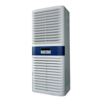
2.6.2 Outdoor unit power cable connection
The three phases (A/B/C) of the power supply are led out from the DISCONNECT switch
of the distribution cabinet and connected to the A/B/C terminals of the main circuit
breaker of the indoor unit respectively. The N/PE wires are connected to the
corresponding terminals. The wiring diagram is as shown in Fig.2-25.
Fig. 2-25 Schematic diagram for the power connection of indoor unit
Distribution cabinet
disconnect switch