Shenzhen Envicool Technology Co., Ltd.
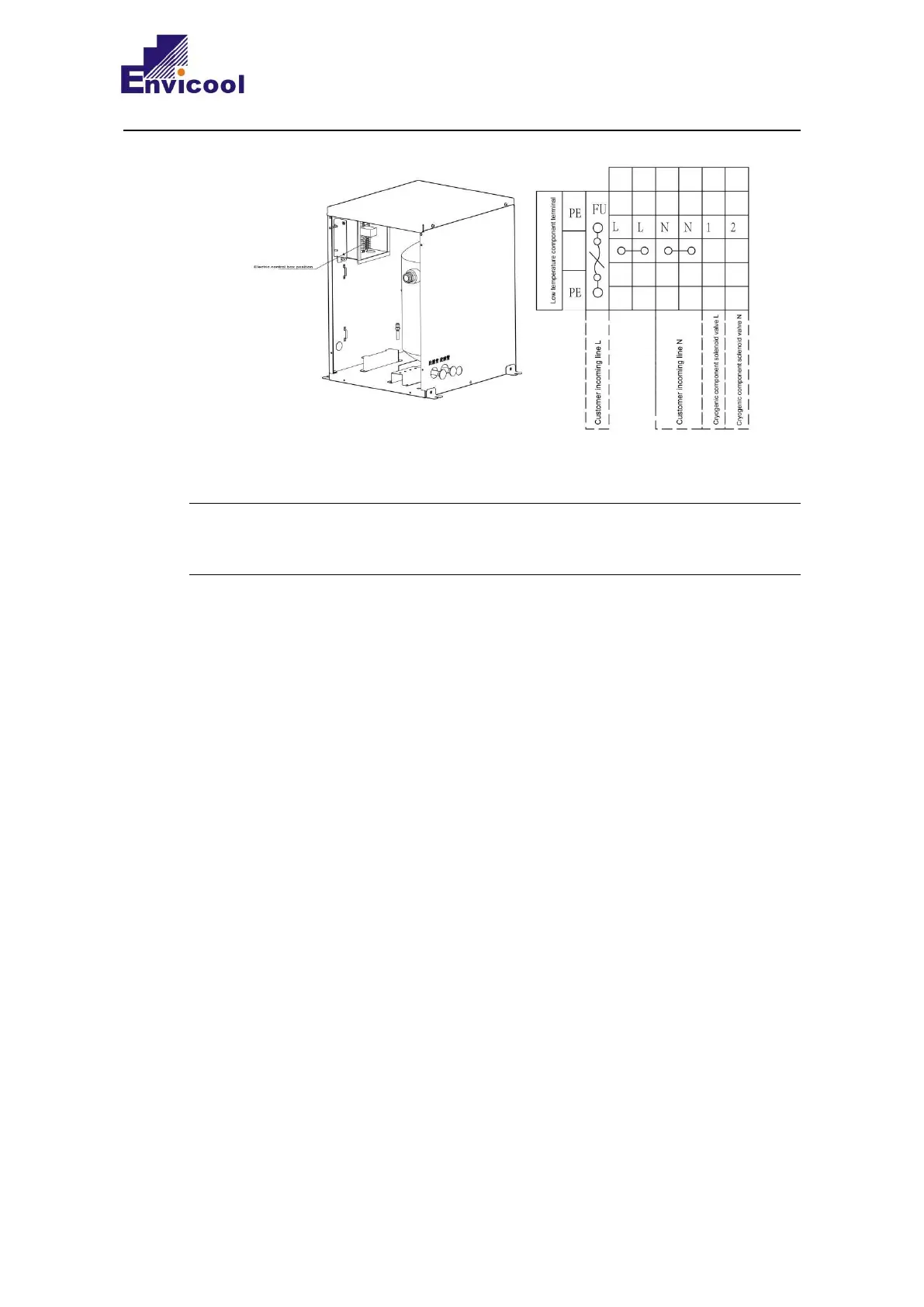
Fig. 2-26 Schematic diagram of electrical connection of cryogenic components
The schematic diagram of control line connection of XRow series is for reference only and the
dedicated wiring diagram pasted on the unit shall prevail in terms of installation.
2.6.5 Unit function output
The location of the XR series unit control interface is shown in Figure 2-27. The partial
enlarged view of the control interface is shown in Figure 2-28~Figure 2-30. The upper part of
the terminal block is connected to the unit, and the lower part is the user control signal line
interface.