Shenzhen Envicool Technology Co., Ltd.
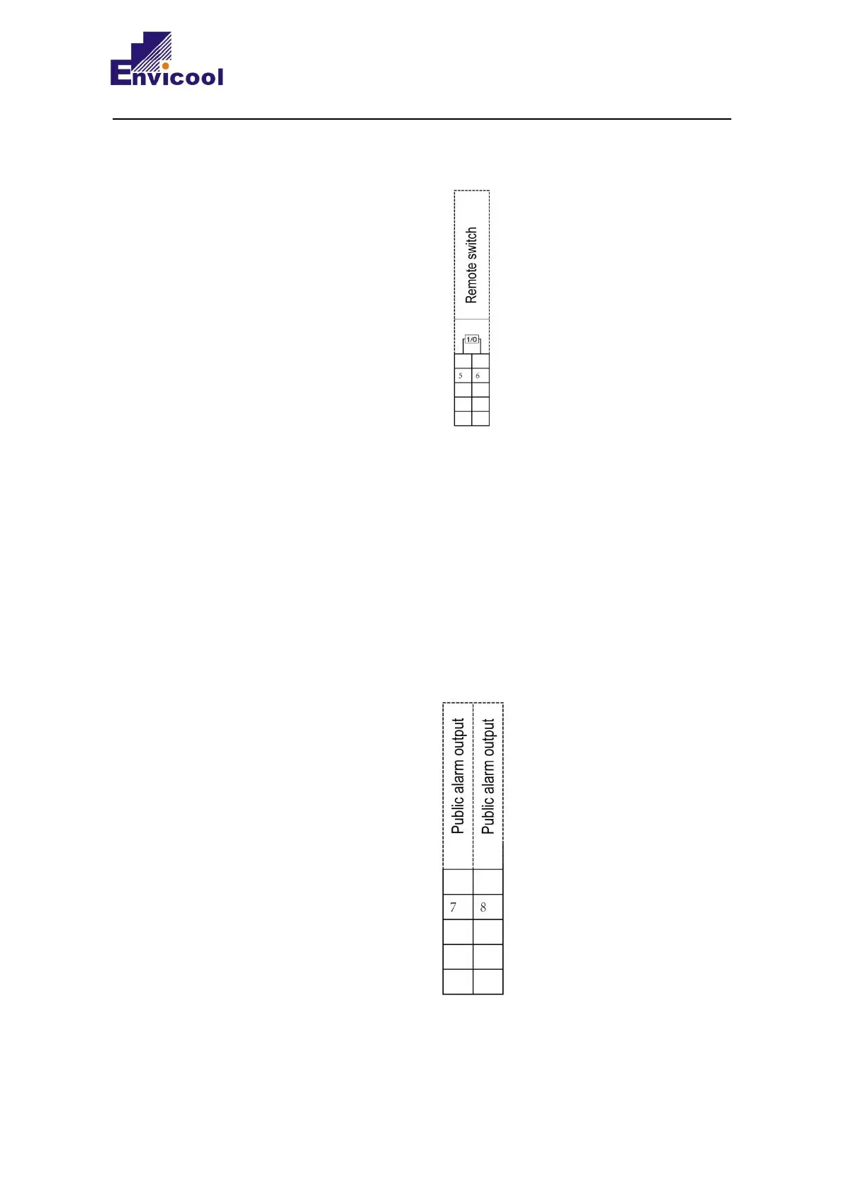
disconnected, the unit is stopped. When the unit leaves the factory, it is connected by
short wiring at the 5/6 position of the terminal block as shown in Figure 2-30.
Figure 2-29 Remote switch machine (active) wiring diagram
The remote switch on/off is an active signal. If multiple units are linked for remote
switch on/off, they cannot be connected in parallel in the project, and signal isolation is
required.
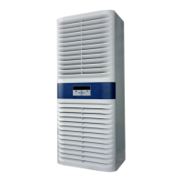
2.6.5.4 Public alarm output
It is recommended that the public alarm output cable adopts shielded cable, and the
cable diameter is not less than 2× 0.5 mm2. The wiring diagram is shown in Figure
2-30.
Figure 2-30 Schematic diagram of public alarm output wiring