FIKE CORPORATION
FM 3020541 Fike Explosion Protection System Page 5 of 32
P/N E06-051 Rev. 8 10/06
ADD
12
MODE
1 234
Cabling from PSU to EPC shall be 0.8 mm
2
(18AWG) minimum not to exceed 10 Ω
resistance.
A keyed selector switch is recommended in the
PSU to EPC power supply cabling to facilitate
reset of the EPC. This shall have a 30V, 1A
rating.
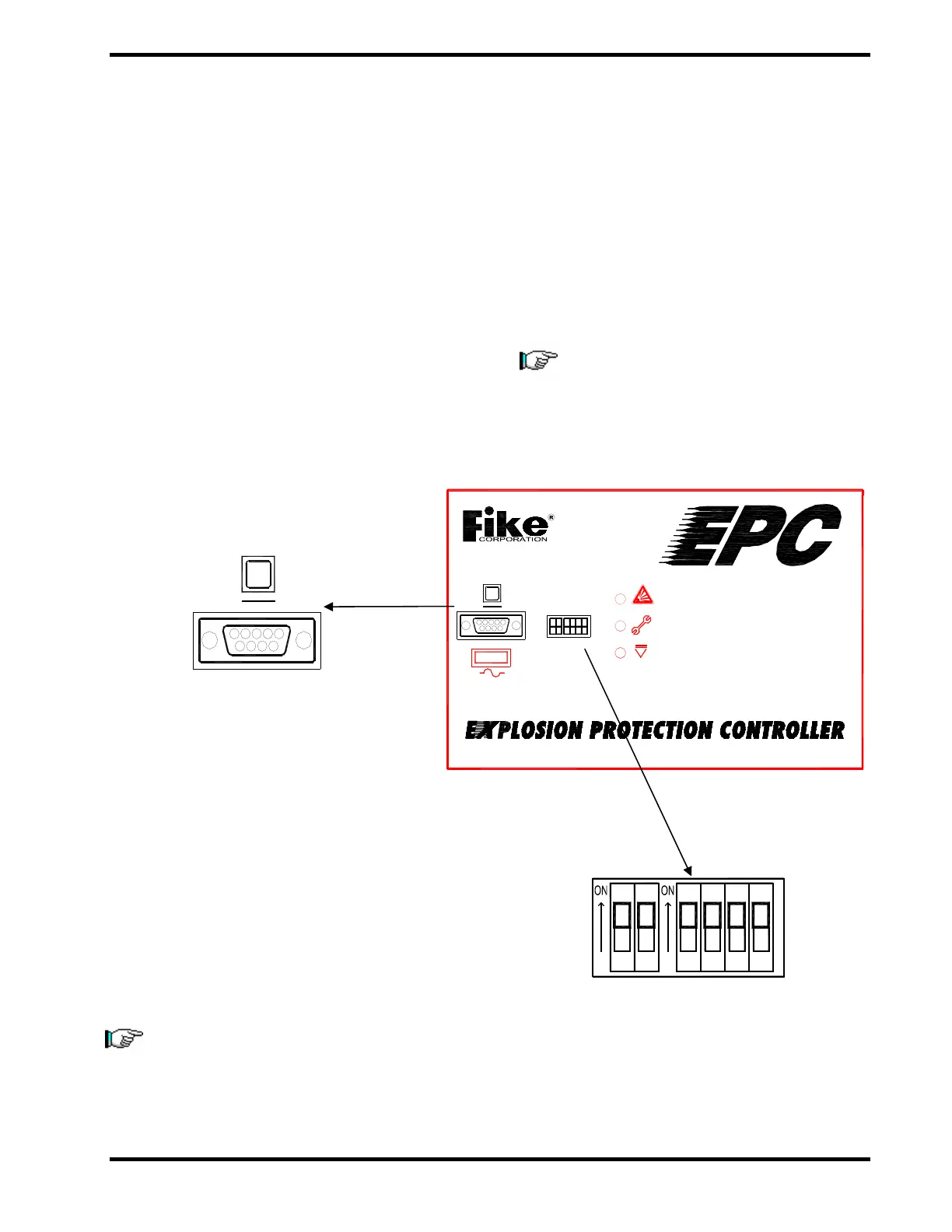
4.3 CONFIGURATION
The EPC, the AM, and the RC8 are all
programmable modules. System configuration
can be performed with DIPswitches on these
modules or by way of a DB9 serial port
connection to a PC using EPWorks™ Software.
EPC addressing is done using the two ADD
(address) DIPswitches. The four MODE DIP
switches are used for programming specific
configurations. Expanded programming may be
created via PC with Fike's EPWorks™ Software.
Exhibit 4-1 Serial Port
The software also is used for extracting system
history information for activation analysis and
other diagnostic activity. Two levels of software
are utilized for the EPACO™ system. Level one
is a read-only user interface for the customer to
check the status/history of his system. Level
two is used by certified service technicians to
program and service customer installations.
NOTE: Address and configuration changes
are to be made by Fike authorized
engineers or technicians only.
4.4 DIP SWITCH CONFIGURATION
The EPACO system can have multiple EPC’s
connected to a single system. The ADD
switches enable the system to distinguish
between multiple EPC’s. The EPC is configured
using the MODE DIP switches on the face of the
unit. The configuration of the DIP switches set
the detection parameters of the EPC. The DIP
switches incorporate a safety feature that
prevents a programming change should one of
the DIP switches inadvertently get changed.
NOTE: The configuration should not be
changed. Any changes in configuration
must be approved by Fike Corporation.
Exhibit 4-2 DIP Switches
DB9
DB9
2A
- 2A -
24VDC
ADD MODE