FIKE CORPORATION
Page 14 of 32 Fike Explosion Protection System FM 3020541
10/06 P/N E06-051 Rev. 8
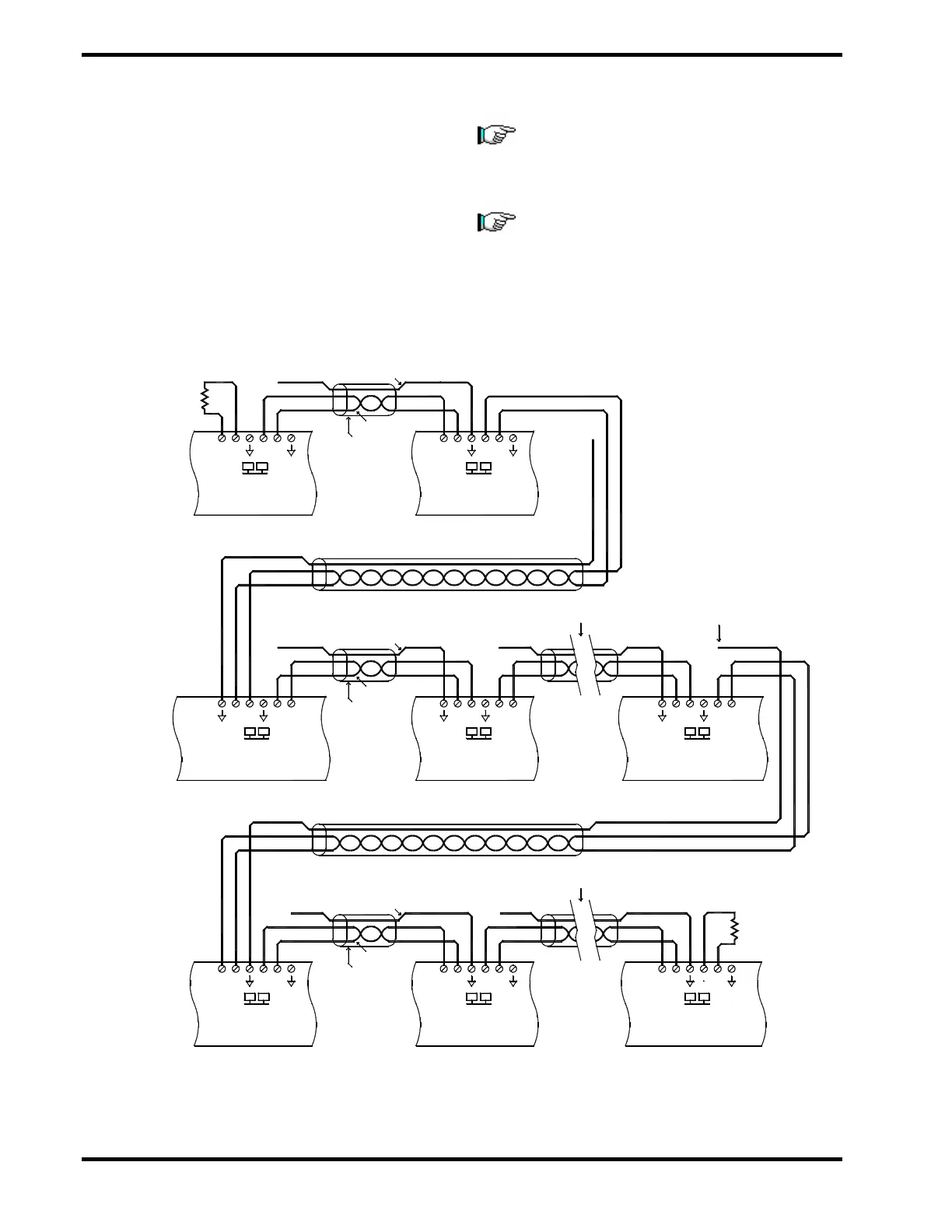
4.8.2 Status Bus (P1-1)
The Status Bus is a low speed communication
bus that transmits control information between
the EPC, Power Supply, Annunciator Module
and Relay Modules. Belden 9841 or RE-Y2Y
cabling is recommended for this circuit.
Maximum resistance R=50 Ω, inductance
L=100uH, and capacitance C=0.02uF with a
maximum length of 300m (1,000 ft).
Note: The B+ connects to the A+ on the next
device; similarly the B– connects to the A– of
the next device. Install the 140 Ω, 1/2 watt
resistor at each end as shown.
Note: The drain wire should only be con-
nected on one end of each wire run. Make
sure that the drain wire, which is not
connected to a terminal, is cut and insulated
from making contact to metal or other wiring
connections.
Exhibit 4-23 Status Bus Wiring
Additional RC8
Twisted Pair
Shield Wire
-
+
-
+
Relay Module
BA
(RC8) #1
P1
Shield
-
+
-
+
BA
RC8 #2
P1
-
+
-
+
Last RC8(Up to 4)
BA
P1
140 ohm
of Drain Wire [ insulate ]
-
+
-
+
-
++
-
Twisted Pair
Shield Wire
Controller (EPC) #1
Explosion Protection
-
++
-
BA
P1
Shield
Annunciator
Module (AM)
BA
++
-
-
BA
P1
EPC #2 Last EPC (Up to 4)
B
-
+
-
P1
A
+
Additional EPC
Unit (PSU)
Power Supply
BA
No termination
Shield Wire
Twisted Pair
140 ohm
P2
Shield
P1