FIKE CORPORATION
Page 10 of 32 Fike Explosion Protection System FM 3020541
10/06 P/N E06-051 Rev. 8
Twisted Pair
Shield
of Drain Wire
No termination
Drain Wire
order to properly supervise cabling.
be mounted at 1st disable device in
Note: Wire Supervision Device shall
820 ohms
240 ohms
Device
End of Line
Device
Contact
Disable
1st
Supervision
Wire
-
+
P4
[ insulate ]
Additional Disable Contacts
Device
820 ohms
End of Line
Device
Series
Contact
Contact
Disable
Last
of Drain Wire
No termination
Twisted Pair
Device
Series
Contact
Contact
1st
Disable
Drain Wire
+
-
Shield
2v4
2v4
[ insulate ]
2.4 volt zener diode
P4
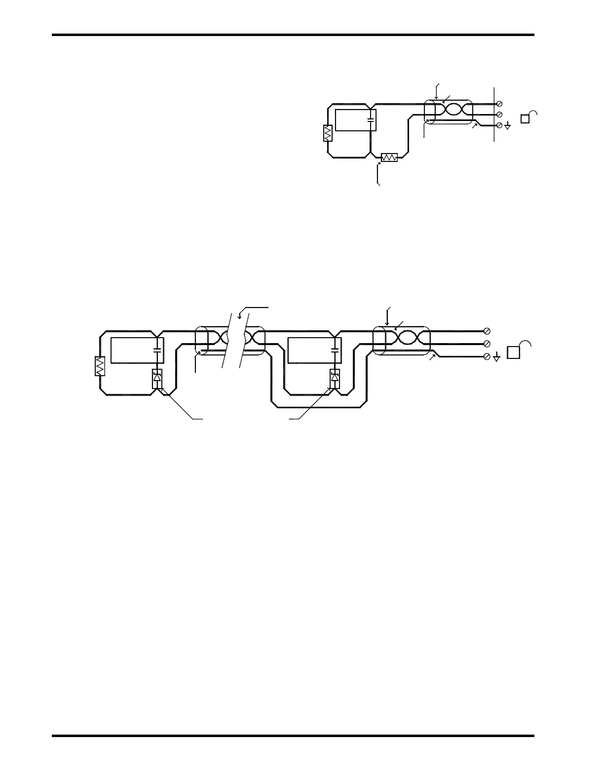
4.6.3 Disable Circuits (P4)
The fifth input contact is for remote disable
(P4-2). The EPC can be disabled with a
command from the AM or from a customer’s
remote PC or other contact device such as a
door switch. Contact closure will initiate the
disable sequence. When the EPC is disabled, a
fire signal cannot be sent out to the GCAs or
other EPCs. Instrument cabling or minimum
2 x 0.5 mm
twisted shielded pair cable
(20 AWG) with drain wire is recommended for
this circuit. Maximum resistance for this circuit
is 30 Ω.
Exhibit 4-13 Disable Circuit – Single Device
Exhibit 4-14 Disable Circuit – Single or Multiple Devices
(Preferred Wiring Method for NO Circuits)