FIKE CORPORATION
FM 3020541 Fike Explosion Protection System Page 11 of 32
P/N E06-051 Rev. 8 10/06
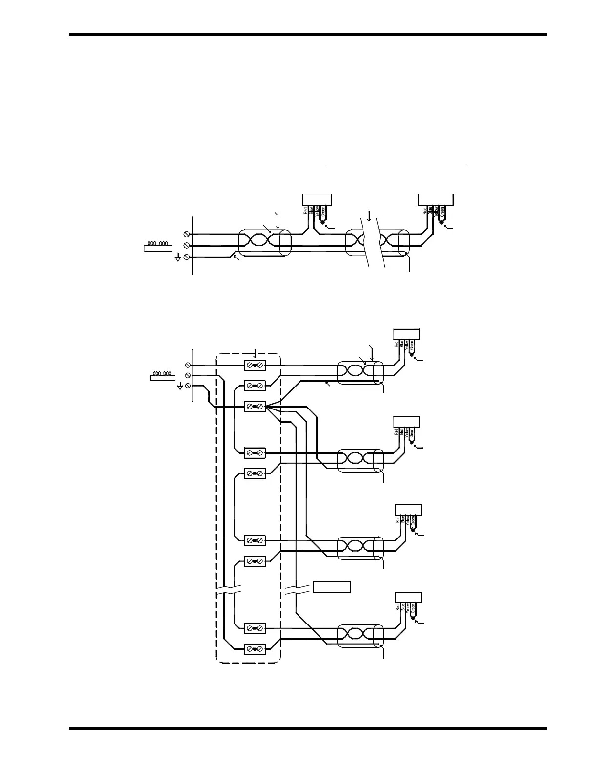
4.7 OUTPUTS
4.7.1 Series Firing Circuit (P3-2)
The main output circuit is the series firing circuit
(P3). This circuit sends the activation signal to
the protection devices to either discharge
suppressant or close isolation valves. The
series firing circuit can activate up to six (6)
actuators
5
. LIY-CY cable or twisted shielded pair
with drain wire is recommended for this circuit.
Total loop length should not exceed 300 m
(1,000 ft) with a maximum distance between any
two connection points of 100 m (300 ft).
Maximum 10 Ω loop resistance, minimum 0.75
mm
(18 AWG), maximum cable section
determined by cable glands and terminals –
refer to component data sheets.
5
FM Approved for use with Fike’s GCA, P/N 02-4134.
Exhibit 4-15 GCA Series Firing Circuit
Exhibit 4-16 Optional GCA Series Firing Circuit
of Drain Wire [ insulate ]
No Termination
Twisted Pair
Shield
Drain Wire
+
-
P3
GCA #1
GCA's 2, 3, 4 & 5
Shunt
Last GCA
Shunt ( & insulate )
No termination
of Drain Wire
of Drain Wire
No termination
No termination
of Drain Wire
No termination
of Drain Wire
(supplied by others)
Terminals located
inside field junction box
+
-
P3
GCA #4, #5
Shield
Twisted Pair
Drain Wire
GCA #6
GCA #3
GCA #2
GCA #1
[ insulate ]
[ insulate ]
[ insulate ]
[ insulate ]
Shunt ( & insulate )
Shunt ( & insulate )
Shunt ( & insulate )
Shunt ( & insulate )