FIKE CORPORATION
FM 3020541 Fike Explosion Protection System Page 1 of 32
P/N E06-051 Rev. 8 10/06
1.0 TERMS AND SYMBOLS USED IN THIS MANUAL
Term/Symbol Description
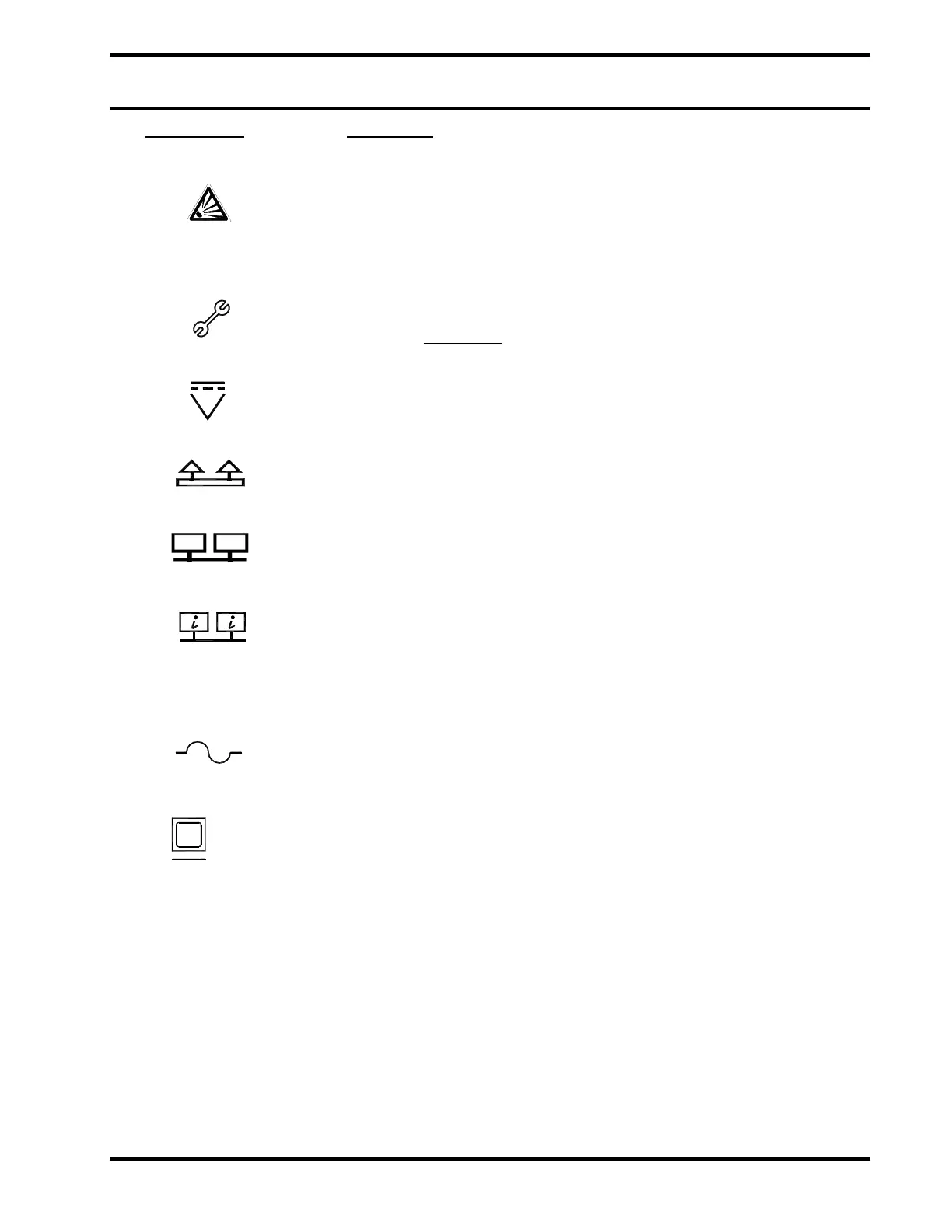
Alarm symbol. This symbol is on the face of the EPC next to the red alarm
LED. This LED will illuminate when the EPC has validated an alarm signal
from a detection device, and as a result, initiated the actuators. (“Alarm”
Red LED ON, Piezo sounding continuous) The alarm occurs when an input
circuit configured for alarm operation has been activated. A detector or
other contact device typically initiates activation.
Trouble symbol. This symbol is on the face of the EPC next to the yellow
trouble LED. This LED will illuminate on any trouble condition where the
EPC’s monitoring system is indicating a fault in one or more of its systems.
The EPC may or may not
be able to provide a response to an activation
signal, depending upon the exact nature of the fault.
DC Power symbol. This symbol is on the face of the EPC next to the green
LED. This LED illuminates at a normal state to indicate that the unit is
receiving power.
Fire Bus symbol. The Fire Bus is a high-speed circuit that sends the fire
signal out to other EPCs in the protection zone and also receives the fire
signal from other EPCs of that protection zone.
Status Bus symbol. The Status Bus circuit is a low speed network
connection that sends status information to other modules. This bus
transmits “state” information to the zones.
Remote Bus symbol. This circuit is a low speed network connection that
sends status information from the Annunciator Modules to a computer for
system monitoring. This network is provided to support future upgrades to
the EPACO system – features associated with this network are currently
not implemented.
Symbol for “ohm”. Unit of resistance.
Fuse symbol. This designation represents a circuit protection fuse. The
fuse is rated at the amperage noted next to this marking.
DB9
Computer Connection symbol. This designation represents the location
for the computer connection. Using a straight-through serial cable, the
PSU can be connected from this DB9 connection to a computer serial port.
The EP Works software can be installed on the computer and provide
operational information.
Actuator An actuator is the electrically actuated firing device used to initiate the
closing of an isolation valve or discharge a suppression container.
Typically actuators are a Gas Cartridge Actuator (GCA) or a detonator.
Cross-zone
Detection
Detection scheme where two detector input channels must activate before
the system releases. The first detector does not latch. This is sometimes
referred to as “AND” configuration.
Disabled State
The condition when the EPC is not allowed to initiate the actuators.
Normal State
The system is in the normal state when the power supply and all circuits are
properly configured, connected, and responding. (Yellow “Trouble” LED
Off, Red “Alarm” LED Off, Green “24VDC” LED On) The system remains in
normal state until a trouble or alarm condition occurs.