FIKE CORPORATION
FM 3020541 Fike Explosion Protection System Page 7 of 32
P/N E06-051 Rev. 8 10/06
Twisted Pair
Last Alarm
820 ohms
Series
Contact
Device
End of Line
Device
Device
Initiating
Initiating
Device
1st Alarm
Device
Contact
Series
Additional Alarm Initiating Devices
No termination
of Shield Wire
Shield
Shield Wire
- -
++
-
+
P3
2v4
2v4
[ insulate ]
2.4 volt zener diode
Twisted Pair
2.4 volt zener diode
Initiating
Contact
Device
Contact
Series
Last Alarm
2v4
Additional Alarm Initiating Devices
Series
Contact
Device
1st Alarm
Contact
Initiating
2v4
Drain Wire
Shield
+
++
- -
-
P3
Shield
Twisted Pair
1 & 2
P2
mA
4-20
-
+
No termination
of Drain Wire [ insulate ]
Drain Wire
-
+
Pressure
Detector
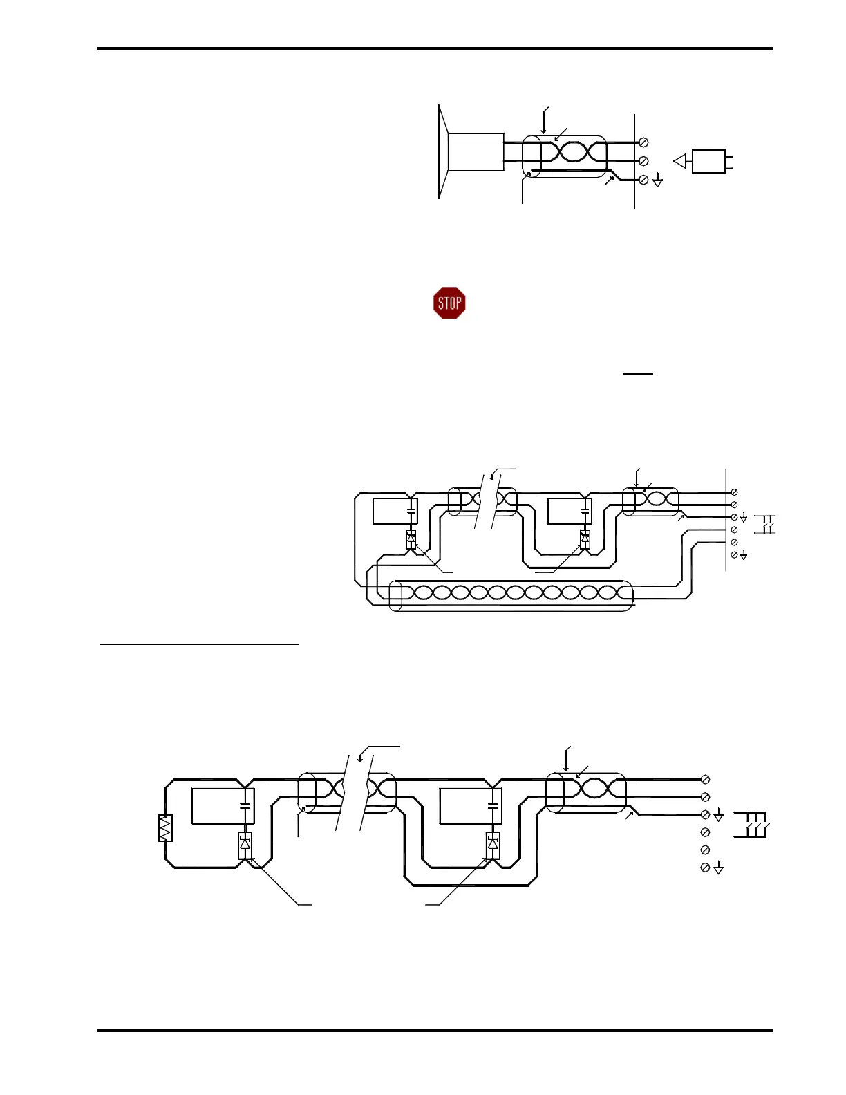
4.6 INPUTS
4.6.1 Detection Inputs (P2 & P3-1)
The first two supervised inputs (P2) are 4-20mA
pressure detector circuits
3
. Only one detector is
permitted on each circuit. These are the primary
detection circuits for the EPACO system.
Instrument cabling or minimum 2 x 0.5 mm
twisted shielded pair cable (20 AWG) with drain
wire is recommended for this circuit. Maximum
resistance for this circuit is 30 Ω.
If the 4-20mA pressure detectors are placed in a
hazardous atmosphere, a Fike approved
transmitter power supply shall be used on each
detection circuit. Detectors used on these
circuits shall be rated for the hazardous location.
The third supervised input (P3) is used for
various “contact closure” type devices and can
be programmed (with EP Works software) for
normally open or normally closed operation. The
default setting is normally open. This could be a
thermal detector, optical detector,
mechanical pressure detector or
similar device
4
. This circuit is
reserved as secondary detection
input, but will activate the protection
system. Instrument cabling or
minimum 2 x 0.5 mm
twisted
shielded pair cable (20 AWG) with
drain wire is recommended for this
circuit. Maximum resistance for this
circuit is 30 Ω.
3
FM Approved for use with Fike’s Ceramic, P/N 29945022-S.
4
FM Approved switch closure for use with Fike threshold
detector (E61-042-x) and Rate of Rise detector (E61-056-x).
Other switch closure, thermal, or infrared devices are not
approved by FM.
Exhibit 4-5 Detection Circuit 1 or 2 (Class B)
WARNING: Transducer Simulator is used to
allow the EPC to enter a normal
state when no transducer is
connected. The Transducer
Simulator must
be removed when
a transducer is connected to the
corresponding P2 input.
Exhibit 4-6 Detection Circuit 3 – NO (Class A)
Exhibit 4-7 Detection Circuit 3 – NO (Class B)