FIKE CORPORATION
FM 3020541 Fike Explosion Protection System Page 13 of 32
P/N E06-051 Rev. 8 10/06
P4
BA
P1 P2 P3
BA
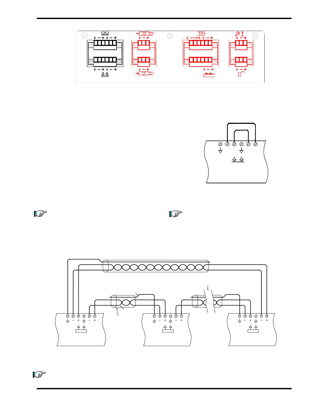
Exhibit 4-20 EPC Top View – P1 Bus Wiring Connections
4.8 BUS COMMUNICATIONS
4.8.1 Fire Bus (P1-2)
The Fire Bus circuit is programmable for output,
input, or both (default). When the EPC has
received the activation signal from its detection
device, it sends a fire signal output through the
fire bus to all EPCs in the protection zone. Any
EPC that is programmed to respond to a fire
signal from this particular EPC will output
through its series firing circuit to discharge its
devices. Belden 9841 or RE-Y2Y cabling is
recommended for this circuit. Maximum
resistance R=50 Ω, inductance L=100uH, and
capacitance C= 0.02uF with a maximum length
of 300 m (1,000 ft).
Exhibit 4-21 EPC Fire Bus – Single EPC
Note: Wiring for a single EPC connects the
B+ to the A– and the B– to the A+. While for
multiple EPCs the B+ connects to the A+ on
the next EPC and the B– connects to the A–
on the next EPC. The Fire Bus must be a
closed loop or Class A bus as shown.
Note: The drain wire should only be con-
nected on one end of each wire run. Make
sure that the drain wire, which is not
connected to a terminal, is cut and insulated
from making contact to metal or other wiring
connections.
Exhibit 4-22 EPC Fire Bus – Multiple EPCs
Note: For proper Fire Bus communication, multiple EPCs connected on the Fire Bus shall be powered
up simultaneously.
P1
A B A
P1
Shield
P1
B
Twisted Pair
Shield Wire
EPC #2
A B
Additional EPCs
Last EPC (Up to 32)
EPC #1
P1
BA
EPC
++
-
-