17
2.4 Install the inverter/charger
Risk of explosion! Never install the inverter/charger in a sealed enclose with flooded
batteries! Do not install the inverter/charger in a confined area where the battery gas
can accumulate.
The inverter/charger can be fixed to the concrete and solid brick walls and cannot
be fixed to the hollow brick wall.
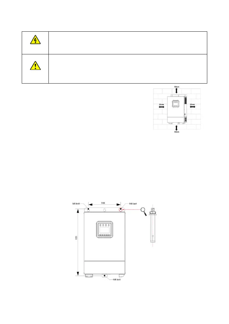
The inverter/charger requires at least 20cm of clearance right and left and 50cm of
clearance above and below.
Step1: Determine the installation location and heat-dissipation space.
The inverter/charger requires at least 20cm of clearance right
and left and 50cm of clearance above and below.
Step2: According to the installation position marked with the mounting plate 1, drill two M10 holes with an
electric drill.
Step3: Insert the screws of the M8 bolts and the steel pipes into the two M10 holes.
Step4: Install the inverter/charger and determine the installation position of the M10 hole (located at the
bottom of the inverter/charge).
Step5: Remove the inverter/charger and drill an M10 hole according to the position determined in step4.
Step6: Insert the screw of the M8 bolt and the steel pipe into the M10 hole.
Step7: Install the inverter/charger and secure the nuts with a sleeve.