46
F. Boost Voltage Reconnect Voltage > Low Voltage Reconnect Voltage
4) In the 48V input voltage system, the following rules must be followed when modifying the
parameter values in the user battery type for a lithium battery.
A. Over Voltage Disconnect Voltage ≥ Over Voltage Reconnect Voltage+1V
B. Over Voltage Disconnect Voltage > Over Voltage Reconnect Voltage = Charging Limit Voltage ≥
Equalize Charging Voltage = Boost Charging Voltage ≥ Float Charging Voltage > Boost Voltage
Reconnect Voltage
C. Low Voltage Reconnect Voltage ≥ Low Voltage Disconnect Voltage+1V
D. Low Voltage Reconnect Voltage > Low Voltage Disconnect Voltage ≥ Discharging Limit Voltage(42.4V)
E. Under Voltage Warning Reconnect Voltage-1V ≥ Under Voltage Warning Voltage ≥ Discharging Limit
Voltage(42.4V)
F. Boost Voltage Reconnect Voltage > Low Voltage Reconnect Voltage
The lithium battery's voltage parameters must be set according to the voltage
parameters of BMS.
3.5.2 Battery control strategy
When the lithium battery protocol and parameters setting accord with anyone of the following cases, the
table (1) control strategy are followed.
Adopt PYLONTECH lithium battery protocol: Set item 40 "PRO" as "11".
Adopt non-PYLONTECH lithium battery protocol: Set item 40 "PRO" as the current lithium battery
protocol number (refer to the UP-Hi Attachment for different lithium battery protocol numbers), and
set item 41 "BEN" as "ON" (enable the BMS function).
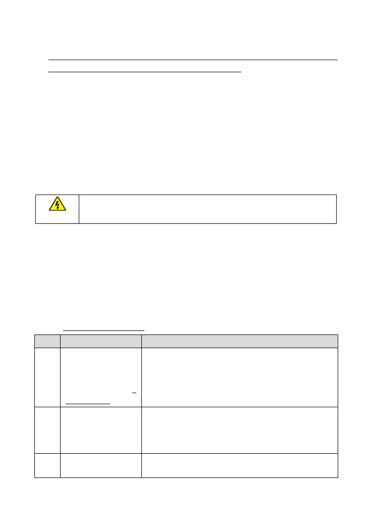
Table (1): Control strategy
The real utility input
voltage is within the
available utility range
(detail range refers to 7
Specifications).
The inverter/charger limits the battery discharge according to
the BMS "discharge current limit".
No BMS "discharge current limit", the inverter/charger limits
the battery discharge according to the limit current set by the
customer.
No utility or the utility
input voltage is beyond
the available utility
range.
The inverter/charger limits the battery discharge according to the
limit current set by the customer.
Battery charge is
requested.
The inverter/charger charges the battery per the charging current
of the BMS.