3. With the Fusion Pro powered o, place the Rotary Attachment in the upper le corner of the table
so that the baseplate is positioned against the sides of the le and top rulers. The rotary rests on
the table against the rulers and does not need to be locked in place.
4. Insert the connector into the receptacle on the right side of the machine.
5. Once the Rotary Attachment is plugged in you can power on the Fusion Pro .
6. When the Fusion Pro powers on with the Rotary Attachment installed, the carriage moves to the
rotary Home position, which is directly above the 3-Jaw Chuck.
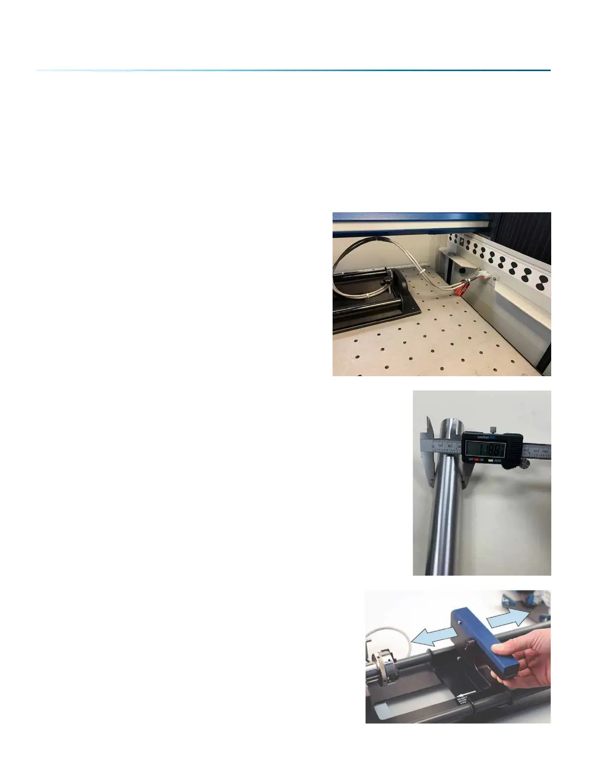
This photo shows plug-in location, located inside of the
laser system cabinet, right side.
3-Jaw Chuck Rotary Attachment Setup
1. Measure your Cylinder: The cylinder diameter will be used in the print
driver.
2. Adjust the Rotary for Cylinder Length: Depress the blue
anodized idle-side handle to move the support mechanism
le or right to accommodate dierent length cylinders.
There are photos later in this section that show the dierent
configurations available for the Y-Axis idle side support.
- 136 -
SECTION 9: OPTIONAL FEATURES
 Loading...