Epson Artisan 810/835/837/710/725/730/Epson Stylus Photo PX810FW/TX810FW/PX820FWD/TX820FWD/PX830FWD/PX710W/TX710W/PX720WD/TX720WD/PX730WD/TX730WD
Revision G
DISASSEMBLY/ASSEMBLY Disassembly Procedures 139
Confidential
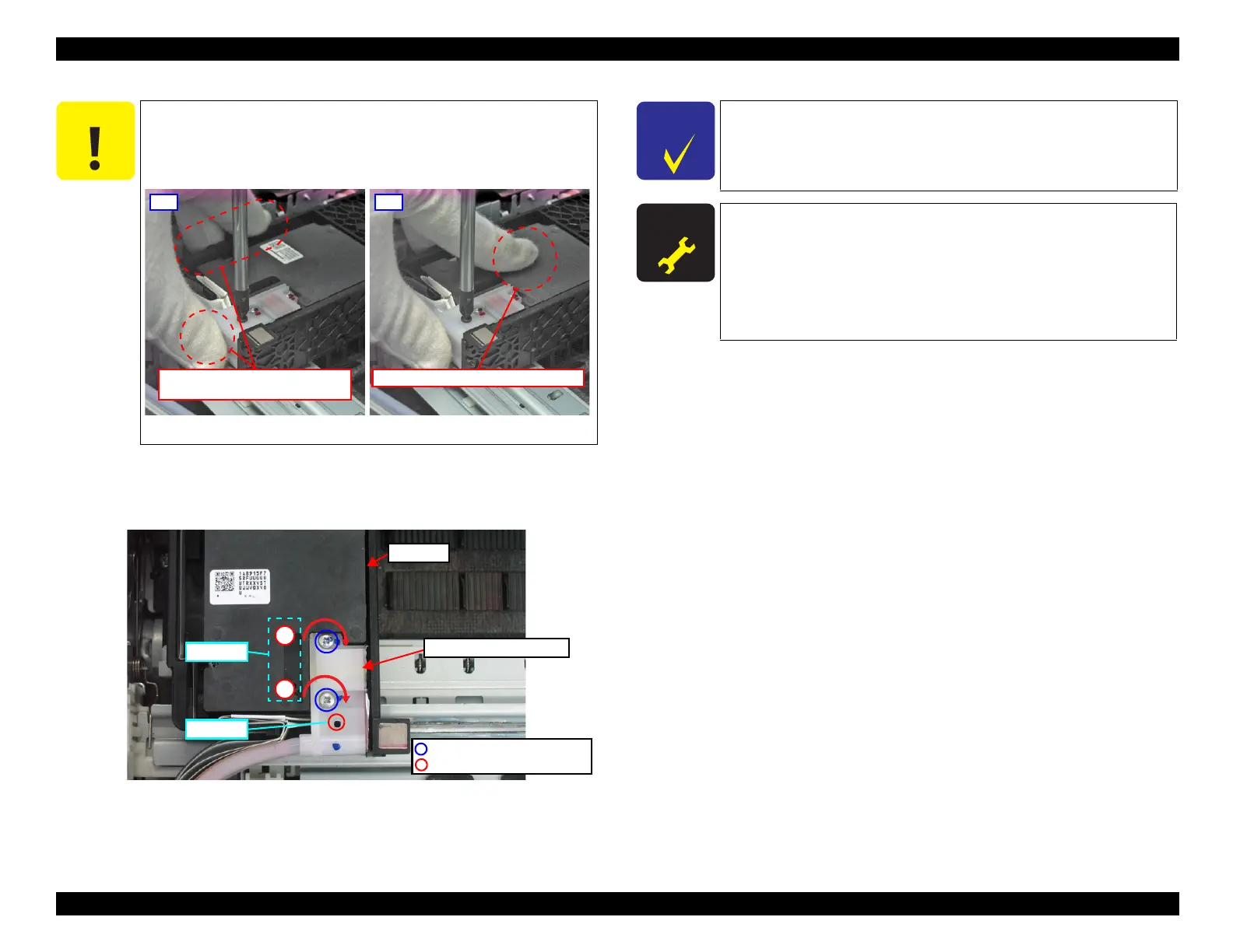
10. Tighten the loosened screws (x2) in Step 9 in the order shown in Fig. 4-68 by 180
degrees.
11. Secure the Ink Supply Tube Assy with the screw.
Figure 4-68. Assembling the Printhead (7)
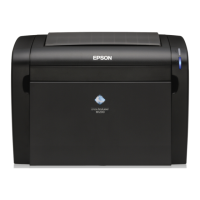
Do not place the finger on the Printhead when tightening the screws
in the next step, otherwise, the frames may be deformed.
Tighten the screws while holding the marked sides of the Carriage
and the Ink Supply Tube Assy in the “OK” figure below.
Figure 4-67. Holding the positions of the Carriage at Screwing
NG
Do not place the finger on the Printhead.
OK
Hold the marked sides of the Carriage
and the Ink Supply Tube Assy.
Ink Supply Tube Assy
Printhead
C.B.P. 2x12 (Black; 3.0±0.5Kgfcm)
1
2
Step 10
Step 11
C.B.P. 2x10 (2.0±0.3Kgfcm)
Confirm that there is no ink penetrating into the Decompression
Tube located inside the Ink Supply Tube Assy. If such ink
penetration is observed, make sure to replace the Ink Supply IC
Holder Assy
(p144) together with the Printhead.
A D J U S T M E N T
R E Q U I R E D
After removing/replacing the Printhead, make the specified
adjustments. (See
Chapter 5 "ADJUSTMENT".)
When disconnecting the joint of the Printhead and the Ink
Tube, in particular, the Leak Check is necessary.
If the position of the notch on the Parallelism Adjustment
Busings have not changed, only “
PG Inspection (p233)” is
necessary.