Epson Artisan 810/835/837/710/725/730/Epson Stylus Photo PX810FW/TX810FW/PX820FWD/TX820FWD/PX830FWD/PX710W/TX710W/PX720WD/TX720WD/PX730WD/TX730WD
Revision G
DISASSEMBLY/ASSEMBLY Disassembly Procedures 145
Confidential
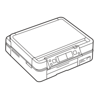
2. Release the hooks (x4) that secure the IC Guide, and remove the IC Guide
from the Cartridge Box Unit.
Figure 4-79. Removing the IC Guide
3. Disconnect the decompression tube from the socket on the Cartridge Box
Unit. (See
Fig. 4-73.)
4. Remove the screws (x7) that secure the Cartridge Box Unit.
Figure 4-80. Removing the Cartridge Box Unit
5. Release the Clamp Tubes (x2). (See Fig. 4-81.)
6. Release the Ink Supply Tube Assy and FFC from the FFC Holder, and remove
the Ink Supply IC Holder Assy.
Figure 4-81. Removing the Ink Supply Tube Assy
IC Guide
Cartridge Box Unit
Hook
Cartridge Box Unit
Grounding
Plate
Right
C.B.P. 3x10 (6±1Kgfcm)C.B.P. 3x8 (6±1Kgfcm)
C.B.P. 3x25 (6±1Kgfcm) C.B.S. 3x4 (4±0.5Kgfcm)
C.B.S. 3x6 (8±1Kgfcm)
To prevent ink leakage, make sure not to separate the Ink Supply
Tube Assy and the Cartridge Box Unit by removing the screws (x2)
on the section A shown in
Fig. 4-81. Loosening the screws on the
section A even just once will cause ink leakage, therefore, make sure
to replace the Ink Supply IC Holder Assy with a new one.
Cartridge Box Unit
Ink Supply Tube Assy
FFC
Clamp
Tube
FFC Holder
Section A