EH-TW3500/4500/5500 Disassembly and Assembly CONFIDENTIAL
SEIKO EPSON 97 Revision A
Standard
Insulation resistance should be 10 MΩ or more.
Testing procedure
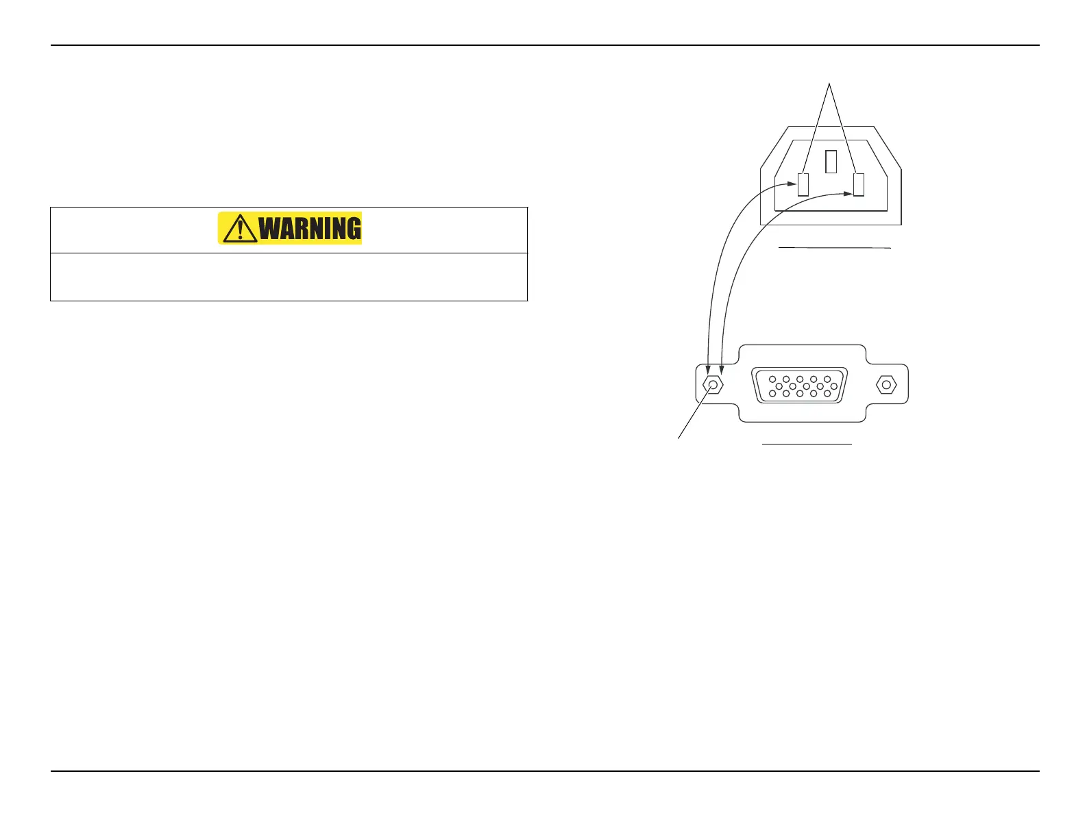
1. Insulation resistance test
1. Set the range selection switch to 500 V.
2. Connect the black lead wire to the ground terminal.
3. Connect the red lead wire to the line terminal.
4. Connect the crocodile clip of the black lead wire to “c” of the PC
connector. (refer to Fig. 3-42)
5. Insert the probe of the red lead wire into “a”.
6. Set the measure switch to LOCK, and wait for one minute.
7. Measure the insulation resistance between “a” and “c” (1) after one
minute.
8. Measure the insulation resistance between “b” and “c” (2) in the same
way as for (1).
Figure 3-42.
Because high voltage (500 V) is present, do not touch the probe during testing.
Power supply lines
Exposed metal part of the device
Projector AC inlet
PC connector
(1)
(2)
C
a
b
 Loading...