EasyManuals Logo

Epson RC700 User Manual

Epson RC700
316 pages
To Next Page IconTo Next Page
To Previous Page IconTo Previous Page
Page #171 background imageLoading...
Page #171 background image
Maintenance 7. Maintenance Parts Replacement Procedures
RC700 / RC700-A Rev.23 159
(9)
RC700:
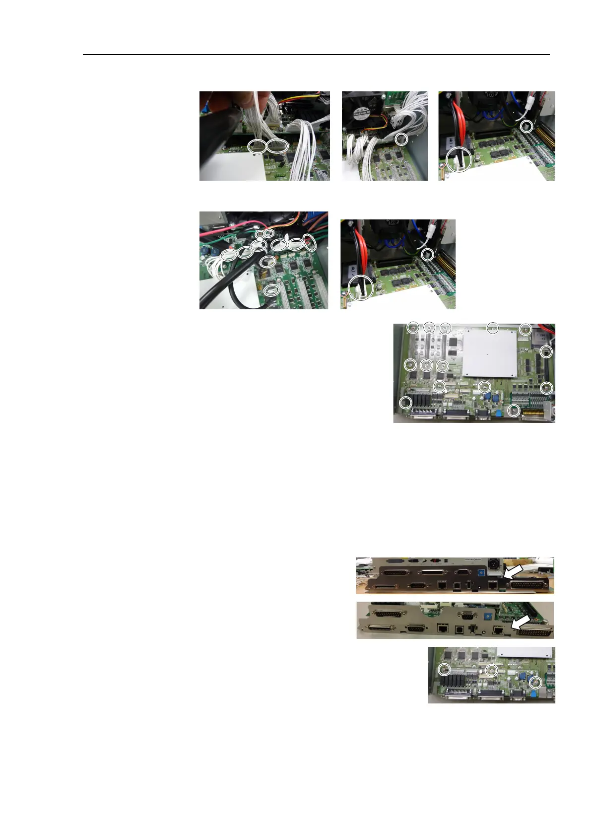
Remove the five connectors from the DMB.
RC700
-A: Remove the twelve connectors from the DMB.
(10)
R
emove the DMB mounting screws (×14).
(11)
Remove the fan.
Refer to Maintenance: 7.2 Fan.
(12)
Remove the DMB from the chassis.
At this point, be
careful not to touch the chassis and other parts.
(13)
Remove the plate fixing the connectors on the front side from the DMB and the
DMB
-SUB boards.
RC700
RC700-A
(14)
Remove the
DMB-SUB board from the DMB.
(Mounting screw
×3)

Table of Contents

Questions and Answers:

Question and Answer IconNeed help?

Do you have a question about the Epson RC700 and is the answer not in the manual?

Epson RC700 Specifications

General IconGeneral
Maximum Axes16
Communication InterfacesEthernet, EtherNet/IP, PROFINET, PROFIBUS, CC-Link, RS-232C, USB
Safety StandardsISO 10218-1, ISO/TS 15066, IEC 61508, IEC 61511, ANSI/RIA R15.06
Operating SystemVxWorks
Power Supply24 VDC

Related product manuals