EasyManuals Logo

Epson RC700 User Manual

Epson RC700
316 pages
To Next Page IconTo Next Page
To Previous Page IconTo Previous Page
Page #173 background imageLoading...
Page #173 background image
Maintenance 7. Maintenance Parts Replacement Procedures
RC700 / RC700-A Rev.23 161
(8)
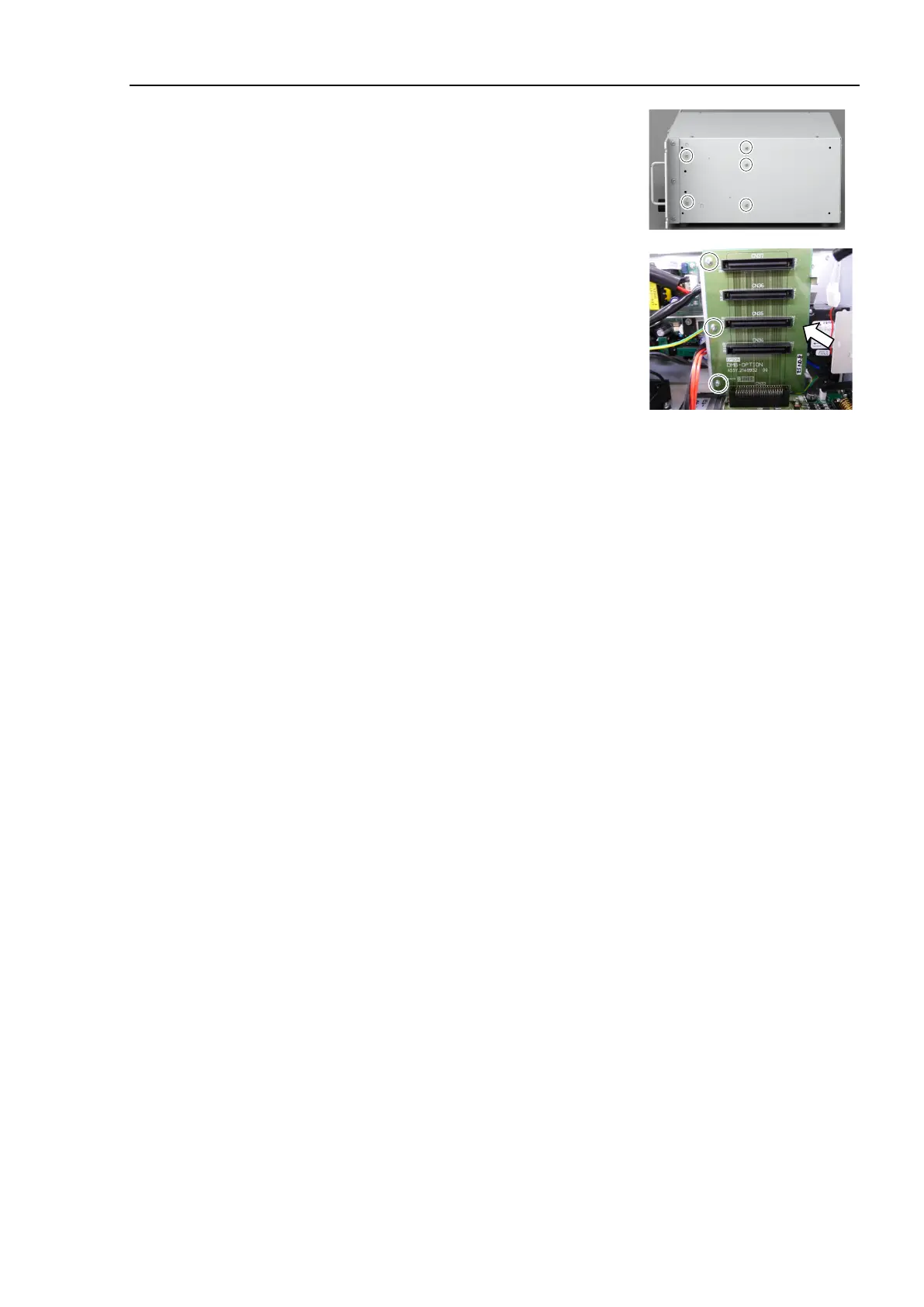
Mount the five screws on the side of the chassis.
(9
)
Mount the DMB
-OPTION board.
(Mounting screw ×3)
(10
)
Mount the MDB.
Refer to
Maintenance: 7.5 MDB.
(11
)
Install the cables to
the following connectors.
M/C Signal Connector EMERGENCY Connector
TP Connector USB Connector
USB Memory Ethernet Connector
I/O Connector RS-232C Connector
R-I/O Connector DU OUT Connector
(12
)
Mount the Top Panel. (Mounting screw
×6)
(13
)
Connect the power plug
. Turn ON the Controller and make sure that the
Controller
starts properly without any vibration or abnormal noise.

Table of Contents

Questions and Answers:

Question and Answer IconNeed help?

Do you have a question about the Epson RC700 and is the answer not in the manual?

Epson RC700 Specifications

General IconGeneral
Maximum Axes16
Communication InterfacesEthernet, EtherNet/IP, PROFINET, PROFIBUS, CC-Link, RS-232C, USB
Safety StandardsISO 10218-1, ISO/TS 15066, IEC 61508, IEC 61511, ANSI/RIA R15.06
Operating SystemVxWorks
Power Supply24 VDC

Related product manuals