EPSON Stylus C67/C68/D68 Revision A
DISASSEMBLY/ASSEMBLY Disassembly Procedures 53
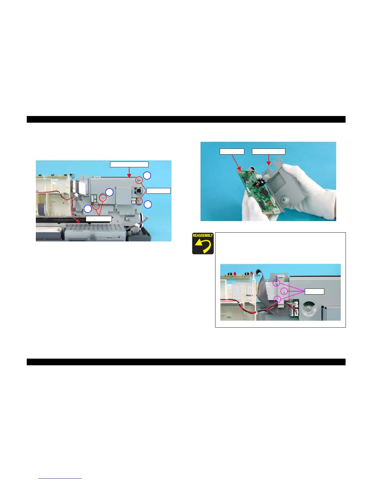
4) Remove the four screws that secure the Main Board Unit to the Main Unit,
and remove the Main Board Unit.
• C.B.S. 3 x 14: 2
• C.B.S. 3 x 6: 2
Figure 4-24. Removing Main Board (2)
5) Remove the Main Board Cover from the Main Board Unit.
Figure 4-25. Removing Main Board (3)
C.B.S. 3 x 14
Main Board Unit
1
2
3
4
C.B.S. 3 x 6
When installing the Main Board Unit to the Main Unit, Secure
the screws in the order shown in Figure 4-24.
When attaching the Clump Core, pay attention not to confuse
left and right. The side with two portions should be facing to the
left.
Figure 4-26. Attaching Clump Core
Main Board Main Board Cover
Portions

 Loading...


