EPSON Stylus C67/C68/D68 Revision A
DISASSEMBLY/ASSEMBLY Disassembly Procedures 55
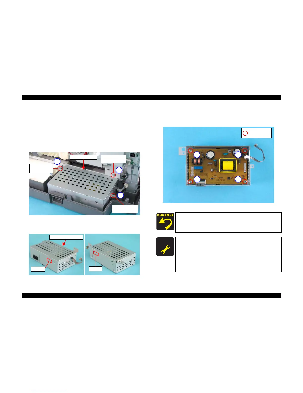
4.3.2.3 PS Board
1) Remove the ASF Unit. (p44)
2) Disconnect the Power Supply Cable (CN2) from the Main Board.
(See 4.3.2.1 Removing Main Board Step 3)
3) Remove the three screws that secure the PS Board Unit to the Main Unit, and
remove the PS Board Unit.
• C.B.P. 3 x 10: 2
• C.B.S. 3 x 6:1
Figure 4-29. Removing PS Board
4) Release the two tabs on both sides of the PS Board Unit, and remove the PS
Board Frame, Upper.
Figure 4-30. Removing PS Board Frame, Upper
5) Remove the four screws that secure the PS Board to the PS Board Frame,
Lower, and remove the PS Board.
• C.B.S 3 x 6: 4
Figure 4-31. Removing PS Board
1
2
3
C.B.P. 3 x 10
(6
±1 kgf.cm)
C.B.S. 3 x 6
(8
±1 kgf.cm)
C.B.P. 3 x 10
(6
±1 kgf.cm)
PS Board Unit
Tab
Tab
PS Board Frame, Upper
When installing the PS Board to the PS Board Frame, Lower,
secure the screws in the order shown in Figure 4-31.
When installing PS Board Unit to the Main Unit, secure the
screws in the order shown in Figure 4-29.
A D J U S T M E N T
R E Q U I R E D
When PS board unit is removed or replaced with new one,
the following adjustment must be performed in the order
below.
1. “Top Margin Adjustment”
2. “PF Adjustment”
3. “First Dot Adjustment”
4. “Offset input for CR Motor Calorific Limitation”
1
23
4
C.B.S. 3 x 6
(6
±1 kgf.cm)

 Loading...


