EPSON Stylus C67/C68/D68 Revision A
DISASSEMBLY/ASSEMBLY Disassembly Procedures 75
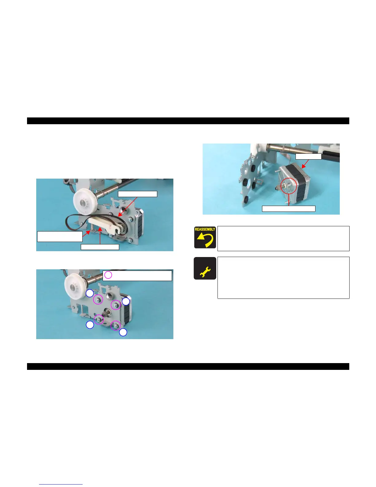
4.3.3.18 PF Motor
1) Remove the Housing, Lower Assy.. (p47)
2) Disconnect the PF Motor Connector from the Main Board.
(See 4.3.2.1 Removing Main Board Step 3)
3) Remove the PF Timing Belt, Idle Roller Assy, and Compression Spring from
the Main Unit.
Figure 4-73. Removing PF Motor (1)
4) Remove the four hexagon nuts that secure the PF Motor to the Main Unit.
Figure 4-74. Removing PF Motor (2)
5) Remove Compression Spring 1.53, and remove the PF Motor.
Figure 4-75. Removing PF Motor (3)
Idle Roller Assy.
PF Timing Belt
Compression Spring
1.13
HEXAGON NAT NORMAL M3
(6
± 1 kgf.cm)
1
3
2
4
When installing the PF Motor, make sure to attach
Compression Spring 1.53 to the part shown in Figure 4-75.
When installing the PF Motor, secure the hexagon nuts in the
order shown in Figure 4-74.
A D J U S T M E N T
R E Q U I R E D
When PF motor is removed or replaced with new one, the
following adjustment must be performed in the order below.
1. “Top Margin Adjustment”
2. “PF Adjustment”
3. “Bi-D Adjustment”
4. “Head Angular Adjustment”
5. “First Dot Adjustment”
Compression Spring 1.53
PF Motor
 Loading...


