EPSON Stylus C67/C68/D68 Revision A
DISASSEMBLY/ASSEMBLY Disassembly Procedures 74
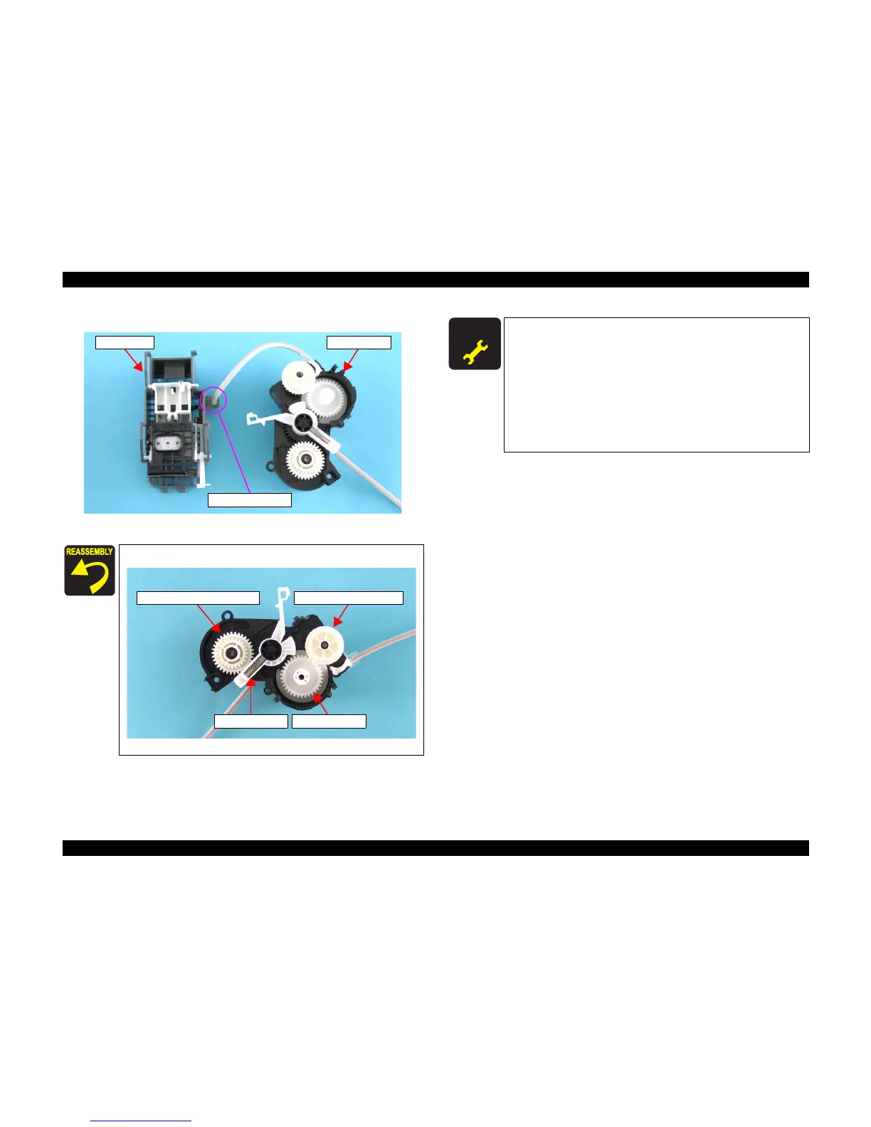
4) Remove the Ink Tube that connects the Pump Unit and the Cap Unit.
Figure 4-71. Removing Pump Unit/Cap Unit (2)
Be sure to assemble the Pump Unit as shown below.
Figure 4-72. Assembling Pump Unit
Cap Unit Pump Unit
Ink Tube Joint
Compound Gear 21, 24Compound Gear 27.2, 19.2
Spool Gear 27.2CR Lock Lever
A D J U S T M E N T
R E Q U I R E D
When you replace Pump Unit/Cap Unit with new one, lubricate
it as specified. See "6.1.3 Lubrication" (p92) for details.
When Pump Unit/Cap Unit is removed or replaced with new
one, the following adjustment must be performed in the order
below.
1. “Top Margin Adjustment”
2. “PF Adjustment”
3. “Bi-D Adjustment”
4. “Head Angular Adjustment”
5. “First Dot Adjustment”

 Loading...


