Do you have a question about the Epson Stylus Pro 3850 and is the answer not in the manual?
Details the manual's structure, including chapters and appendix.
Explains the meaning of symbols used for warnings and important information.
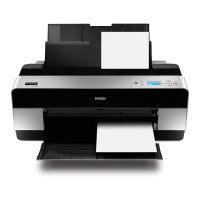
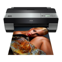
Provides a general overview and specifications of the Epson Stylus Pro printers.
Lists key technical specifications including paper width, printing method, and ink system.
Details printing specifications, including paper feed methods and size support.
Details print modes, quality settings, print density, and borderless printing capabilities.
Details the printer's external dimensions, weight, and identifies key parts.
Explains the operation panel, buttons, functions, LEDs, and display indicators.
Provides a high-level overview of the printer's operational mechanisms.
Explains the basic specifications of the print head and nozzle configuration.
Details the ink supply mechanism, including flow paths and pressurizing systems.
Explains the printer's cleaning mechanism, including pump cap unit and waste ink pads.
Details the carriage mechanism, including movement, platen gap, and lock systems.
Explains the paper feed mechanism, including paths and loading processes.
Describes the ink mark sensor's function, location, and its use in various adjustments.
Covers other mechanisms like ink cover and maintenance cartridge cover detection.
Summarizes the main circuit boards and their functions, including block diagrams.
Explains Colorimetric Calibration (Color ID) for correcting unit-to-unit color variations.
Provides an overview and basic procedures for quick and efficient printer troubleshooting.
Lists panel messages displayed on the printer's LCD, detailing descriptions and reference pages.
Explains remedies for warning messages displayed on the printer's LCD.
Details remedies for various error messages displayed on the printer's LCD.
Provides remedies for service call errors, including error codes and their solutions.
Provides troubleshooting steps for common print quality issues like dot missing and ink smear.
Introduces the procedures for disassembling and reassembling printer components.
Lists essential safety precautions to be followed before starting disassembly or reassembly.
Defines the printer's orientation for disassembly procedures.
Lists the specific tools required for safe and proper disassembly and assembly.
Details the types of screws used in the printer for disassembly and assembly.
Notes on part compatibility between different Epson Stylus Pro models.
Presents a flowchart illustrating the sequence of disassembly procedures.
Details disassembly/assembly procedures for Group 1 components for on-site and off-site servicing.
Details disassembly/assembly procedures for Group 2 components, specifically for off-site servicing.
Introduces the Adjustment Program utility and procedures required after repair or part replacement.
Lists essential cautions to observe when performing printer adjustments.
Outlines the workflow for performing required adjustments based on repaired or replaced parts.
Lists parts and units that require adjustments after repair or replacement.
Details specific adjustments required for each part/unit, including order of execution.
Provides a general outline of the various mechanical and standard adjustments available.
Lists the specific tools and software required for performing printer adjustments.
Explains basic operations and system requirements for the Adjustment Program software.
Details mechanical adjustments, including PF timing belt tension and roller position.
Details standard adjustments performed using software, such as RTC/USB ID and Head Rank ID.
Describes procedures for checking adjustment results, including nozzle checks and print images.
Explains how to reset service life counters after replacing or repairing parts.
Provides information on maintaining the printer for optimum operating condition.
Details the product life information for various parts, including maintenance and service call thresholds.
Provides instructions for cleaning specific printer components like the platen and paper feed path.
Details lubrication points, required lubricants, amounts, and application procedures.
Lists and describes the connectors on the main, power supply, panel, and CR relay boards.
Illustrates how FFCs and cables are routed inside the printer for proper connectivity.
Lists After Service Parts (ASP) with reference numbers for ordering.
Provides exploded diagrams of printer components for service and identification.
Provides circuit diagrams for the main, panel, sub, PSB, and PSE boards of the printer.