1. Safety
Safety and Installation (T, VT / EPSON RC+ 7.0) Rev.15 11
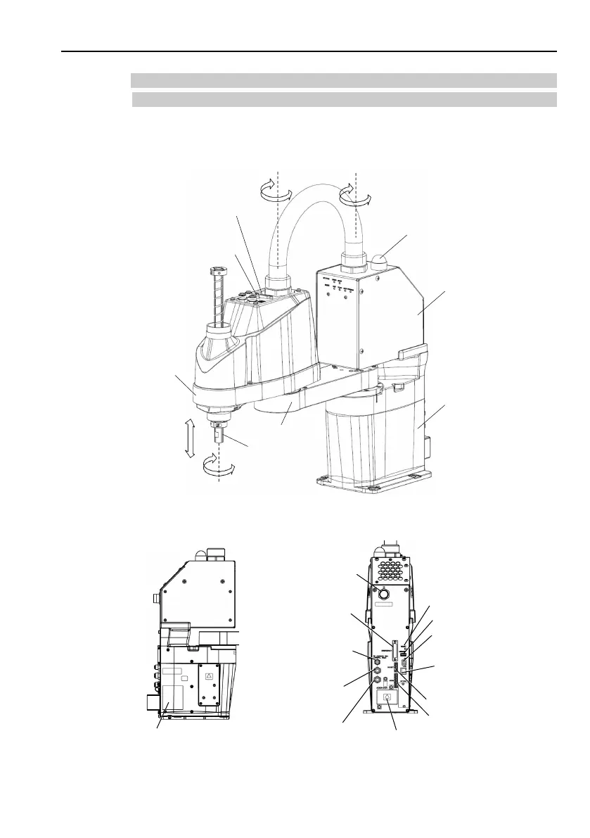
1.3.2 Part Names / Arm Motion
T series Manipulator
The motion range of each arm is shown in the figure below. Take all
necessary safety precautions.
Joint #3
Brake Release Switch
Joint #1
(Rotation)
Joint #2
(Rotation)
Joint #3
(Up/Down)
Joint #4
(Rotation)
Arm #1
Arm #2
+
−
+
−
+
−
+
−
Shaft
LED Lamp
Power Unit
Base
Hand I/O Connecter
(Illustration: T3-401S)
Signature label
(Serial No. of Manipulator)
Fittings (blue) for ø4 mm
pneumatic tube
Fittings (blue) for ø6 mm
pneumatic tube
TP Connecter
EMERGENCY
Connecter
Power Supply Cover
(AC power connector inside)
I/O (Input) Connector
I/O (Output) Connector
LAN (Ethernet)
Connecter
Port of PC
for development
RESET switch
Fittings (white) for ø6 mm
pneumatic tube
Memory Port
 Loading...


